A use case describes how a user uses a system to accomplish a particular goal. A use case diagram consists of the system, the related use cases and actors and relates these to each other to visualize: what is being described? (system), who is using the system? (actors) and what do the actors want to achieve? (use cases), thus, use cases help ensure that the correct system is developed by capturing the requirements from the user?s point of view.
A use case diagram is usually simple. It does not show the detail of the use cases:
- It only summarizes some of the relationships between use cases, actors, and systems.
- It does not show the order in which steps are performed to achieve the goals of each use case.
As said, a use case diagram should be simple and contains only a few shapes. If yours contain more than 20 use cases, you are probably mis-using usecase diagram.
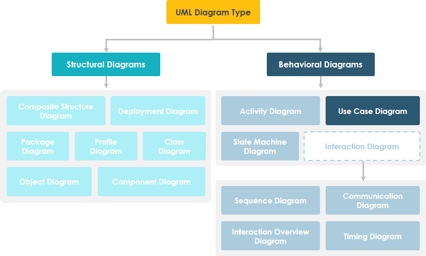
The figure below shows the UML diagram hierarchy and the positioning of UML Use Case Diagram. As you can see, use case diagrams belong to the family of behavioral diagrams.
Use Case Diagram at a Glance
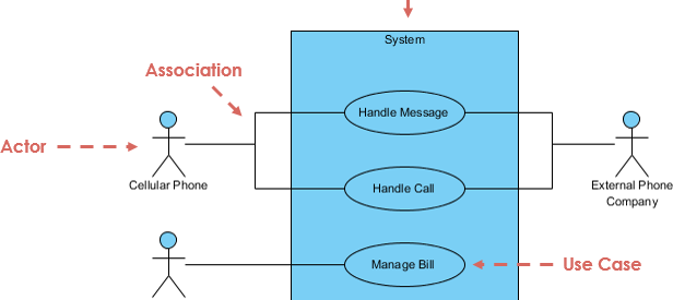
A standard form of use case diagram is defined in the Unified Modeling Language as shown in the Use Case Diagram example below:
Notation DescriptionVisual Representation
Actor
- Someone interacts with use case (system function).
- Named by noun.
- Actor plays a role in the business
- Similar to the concept of user, but a user can play different roles
- For example:
- A prof. can be instructor and also researcher
- plays 2 roles with two systems
- Actor triggers use case(s).
- Actor has responsibility toward the system (inputs), and Actor have expectations from the system (outputs).
![]()
Use Case
- System function (process ? automated or manual)
- Named by verb + Noun (or Noun Phrase).
- i.e. Do something
- Each Actor must be linked to a use case, while some use cases may not be linked to actors.
![]()
Communication Link
- The participation of an actor in a use case is shown by connecting a actor to a use case by a solid link.
- Actors may be connected to use cases by associations, indicating that the actor and the use case communicate with one another using messages.
![]()
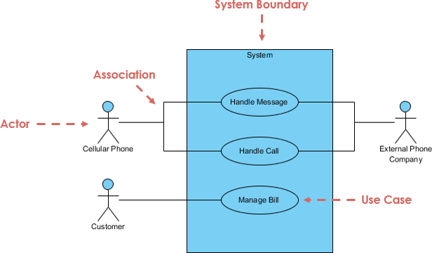
Boundary of system
- The system boundary is potentially the entire system as defined in the requirements document.
- For large and complex systems, each modules may be the system boundary.
- For example, for an ERP system for an organization, each of the modules such as personal, payroll, accounting, etc.
- can form a system boundary for use cases specific to each of these business functions.
- The entire system can span all of these modules depicting the overall system boundary
Structuring Use Case Diagram with Relationships
Use cases share different kinds of relationships. Defining the relationship between two use cases is the decision of the software analysts of the use case diagram. A relationship between two use cases is basically modeling the dependency between the two use cases. Reuse of an existing use case by using different types of relationships reduces the overall effort required in developing a system. Use case relationships are listed as the following:
Use Case Relationship ? Visual Representation
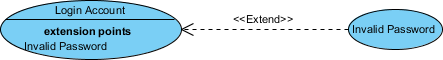
Extends
- Indicates that an ?Invalid Password? use case may include (subject to specified in the extension) the behavior specified by base use case ?Login Account?.
- Depict with a directed arrow having a dotted line. The tip of arrowhead points to the base use case and the child use case is connected at the base of the arrow.
- The stereotype ?<<extends>>? identifies as an extend relationship
Include
- When a use case is depicted as using functionality of another functionality of another use case, this relationship between the use cases is named as an include or uses relationship.
- A use case includes the functionality described in another use case as a part of its business process flow.
- A uses relationship from base use case to child use case indicates that an instance of the base use case will include the behavior as specified in the child use case.
- An include relationship is depicted with a directed arrow having a dotted line. The tip of arrowhead points to the child use case and the parent use case connected at base of the arrow.
- The stereotype ?<<include>>? identifies the relationship as an include relationship.
![]()
Generalization
- A generalization relationship is a parent-child relationship between use cases.
- The child use case in the generalization relationship has the underlying business process meaning, but is an enhancement of the parent use case.
- Generalization is shown as a directed arrow with a triangle arrowhead.
- The child use case is connected at the base of the arrow. The tip of the arrow is connected to the parent use case.
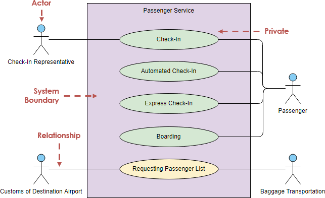
Learn By Examples ? Passenger Service
Here is a use case diagram example for passenger service, let?s take a look. In the use case model there are 4 actors: check-in representative, customs of destination airport, passenger and baggage transportation. They interact with the system to achieve various business goals, as modeled by use cases check-in, automated check-in, express check-in, boarding and request passenger list.
Use this use case diagram template to create your own diagram.
Simply Click Use this Template to edit, or click Create Blank to draw from scratch.
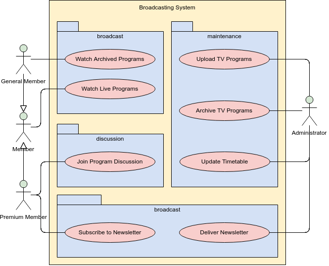
Learn by Examples ? Broadcasting System (Use Case Package)
This is a use case diagram example for an online broadcasting system. Users like general member and administrator are represented as actors, while the business goals of the system, for instance, watch archived and live programs, join program discussion, upload TV programs, are represented as use cases (i.e. the oval shapes). This use case diagram uses system boundary and package shapes in organizing the use cases. This is not a must but doing so makes the whole use case diagram well-organized. Besides, the use of generalization in linking General/Premium Member with Member models the fact that the behavior defined for Member is shared among General and Premium Member.
Use this use case diagram template to create your own diagram.
Simply Click Use this Template to edit, or click Create Blank to draw from scratch.
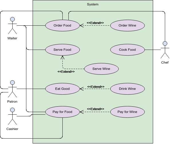
Learn by Examples ? Structuring Use Cases with Include and Extend
This use case diagram example depicts a model of several business use cases. The use case model represents the interactions between a restaurant (the business system) and its primary stakeholders (business actors and business workers). After the base use cases have been identified, you can structure those use case with <> and <> use cases for better clarity.
Use this use case diagram template to create your own diagram.
Simply Click Use this Template to edit, or click Create Blank to draw from scratch.
Other UML Articles
Unified Modeling Language (UML)
- What is UML?
- Why UML Modeling?
- Overview of the 14 UML Diagram Types
- What is Class Diagram?
- What is Component Diagram?
- What is Deployment Diagram?
- What is Object Diagram?
- What is Package Diagram?
- What is Composite Structure Diagram?
- What is Profile Diagram?
- What is Use Case Diagram?
- What is Activity Diagram?
- What is State Machine Diagram?
- What is Sequence Diagram?
- What is Communication Diagram?
- What is Interaction Overview Diagram?
- What is Timing Diagram
- What is UML Collaboration Diagram?
- UML Association vs Aggregation vs Composition
- UML Class Diagram Tutorial
- State Machine Diagram vs Activity Diagram

