
Introduction to object-oriented analysis and design.

This is a series of tutorials. We are going cover:
- An introduction to object-oriented analysis and design.
- System modeling.
- Conceptual model.
- Structural, Interaction, and Behavioral models.
- Design principles and Design patterns.
The Concept Of Object-Orientation
Object-orientation is what?s referred to as a programming paradigm. It?s not a language itself but a set of concepts that is supported by many languages.
If you aren?t familiar with the concepts of object-orientation, you may take a look at The Story of Object-Oriented Programming.
If everything we do in these languages is object-oriented, it means, we are oriented or focused around objects.
Now in an object-oriented language, this one large program will instead be split apart into self contained objects, almost like having several mini-programs, each object representing a different part of the application.
And each object contains its own data and its own logic, and they communicate between themselves.
These objects aren?t random. They represent the way you talk and think about the problem you are trying to solve in your real life.
They represent things like employees, images, bank accounts, spaceships, asteroids, video segment, audio files, or whatever exists in your program.
Object-Oriented Analysis And Design (OOAD)
It?s a structured method for analyzing, designing a system by applying the object-orientated concepts, and develop a set of graphical system models during the development life cycle of the software.
OOAD In The SDLC
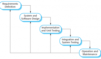
The software life cycle is typically divided up into stages going from abstract descriptions of the problem to designs then to code and testing and finally to deployment.
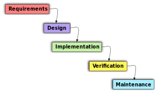
The earliest stages of this process are analysis (requirements) and design.
The distinction between analysis and design is often described as ?what Vs how?.
In analysis developers work with users and domain experts to define what the system is supposed to do. Implementation details are supposed to be mostly or totally ignored at this phase.
The goal of the analysis phase is to create a model of the system regardless of constraints such as appropriate technology. This is typically done via use cases and abstract definition of the most important objects using conceptual model.
The design phase refines the analysis model and applies the needed technology and other implementation constrains.
It focuses on describing the objects, their attributes, behavior, and interactions. The design model should have all the details required so that programmers can implement the design in code.
They?re best conducted in an iterative and incremental software methodologies. So, the activities of OOAD and the developed models aren?t done once, we will revisit and refine these steps continually.
Object-Oriented Analysis
In the object-oriented analysis, we ?
- Elicit requirements: Define what does the software need to do, and what?s the problem the software trying to solve.
- Specify requirements: Describe the requirements, usually, using use cases (and scenarios) or user stories.
- Conceptual model: Identify the important objects, refine them, and define their relationships and behavior and draw them in a simple diagram.
We?re not going to cover the first two activities, just the last one. These are already explained in detail in Requirements Engineering.
Object-Oriented Design
The analysis phase identifies the objects, their relationship, and behavior using the conceptual model (an abstract definition for the objects).
While in design phase, we describe these objects (by creating class diagram from conceptual diagram ? usually mapping conceptual model to class diagram), their attributes, behavior, and interactions.
In addition to applying the software design principles and patterns which will be covered in later tutorials.
The input for object-oriented design is provided by the output of object-oriented analysis. But, analysis and design may occur in parallel, and the results of one activity can be used by the other.
In the object-oriented design, we ?
- Describe the classes and their relationships using class diagram.
- Describe the interaction between the objects using sequence diagram.
- Apply software design principles and design patterns.
A class diagram gives a visual representation of the classes you need. And here is where you get to be really specific about object-oriented principles like inheritance and polymorphism.
Describing the interactions between those objects lets you better understand the responsibilities of the different objects, the behaviors they need to have.
? Other diagrams
There are many other diagrams we can use to model the system from different perspectives; interactions between objects, structure of the system, or the behavior of the system and how it responds to events.
It?s always about selecting the right diagram for the right need. You should realize which diagrams will be useful when thinking about or discussing a situation that isn?t clear.
System modeling and the different models we can use will be discussed next.
System Modeling
System modeling is the process of developing models of the system, with each model representing a different perspectives of that system.
The most important aspect about a system model is that it leaves out detail; It?s an abstract representation of the system.
The models are usually based on graphical notation, which is almost always based on the notations in the Unified Modeling Language (UML). Other models of the system like mathematical model; a detailed system description.
Models are used during the analysis process to help to elicit the requirements, during the design process to describe the system to engineers, and after implementation to document the system structure and operation.
Different Perspectives
We may develop a model to represent the system from different perspectives.
- External, where you model the context or the environment of the system.
- Interaction, where you model the interaction between components of a system, or between a system and other systems.
- Structural, where you model the organization of the system, or the structure of the data being processed by the system.
- Behavioral, where you model the dynamic behavior of the system and how it respond to events.
Unified Modeling Language (UML)
The unified modeling language become the standard modeling language for object-oriented modeling. It has many diagrams, however, the most diagrams that are commonly used are:
- Use case diagram: It shows the interaction between a system and it?s environment (users or systems) within a particular situation.
- Class diagram: It shows the different objects, their relationship, their behaviors, and attributes.
- Sequence diagram: It shows the interactions between the different objects in the system, and between actors and the objects in a system.
- State machine diagram: It shows how the system respond to external and internal events.
- Activity diagram: It shows the flow of the data between the processes in the system.
You can do diagramming work on paper or on a whiteboard, at least in the initial stages of a project. But there are some diagramming tools that will help you to draw these UML diagrams.

)
)