 I2C vs SPI
A communication protocol is a system that allows two or more entities to talk to each other in a communications system. Communication protocols describe communication rules, syntax, rules, and how the device can recover from errors. Like human beings, communication protocols allow data transmission between hardware, software or a combination of the two with different languages.
In this post, I will discuss the differences between I2C and SPI (I2C vs SPI), although there are many serial communications protocols the I2C and SPI are very well-known. I2C and SPI are both bus protocols that enable the user to transfer serial, short-distance data.
What is I2C Protocol?
I2C stands for ?inter-Integrated Circuit bus?. It is also called as I2C. I2C is a two-wire serial protocol for connecting low-speed devices such as microcontrollers, EEPROMs, Analog to Digital (A/D) and Digital to Analog (D/A) converters, Input/Output (I/O) interfaces and other similar peripherals in an embedded system.
The I2C bus is famous because it is easy to use, it can have more than one master and multiple slaves, only upper bus speed is defined and only two wires with pull-up resistors are needed to connect a nearly unlimited number of I2C devices. I2C can use even slower microcontrollers with general-purpose I/O pins because they only need to create appropriate Start and Stop conditions, in addition, to read and write byte functions.
I2C requires just 2 wires to transfer data between devices:
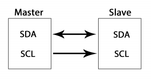 I2C Communication
- SCL (Serial Clock)-The clock signal line.
- SDA (Serial Data)-The line for sending and receiving data between master and slave.
I2C is a serial communication protocol and the SDA line is used to transmit the data bit by bit.
History of I2C protocol:
The I2C bus protocol was invented by Philips Semiconductors in the early 1980s. Its primary purpose was to provide a convenient way to connect a CPU to peripheral chips on a TV set. Today, however, I2C is used in a wide range of communication applications, from LCD to Factory Automation.
It was originally developed for Philips chips. The original standard permitted only 100kHz transmissions and afforded only 7-bit addresses and limits the number of devices on the bus only 112. The first public specification was published in 1992, adding a fast-mode of 400kHz as well as an expanded address space of 10-bits. Three additional modes were also added later: fast mode plus-1MHz; high-speed mode, 3.4MHz; and ultra-fast mode, 5MHz.
How I2C work?
Now you might be thinking how two wires can be used to send data from a master to multiple slaves. Well, for that each device is provided preset ID or a unique device address so that the master can select which devices to use. Serial Clock (or SCL) and Serial Data (or SDA) are the two wires or lines. The SCL line is used to transmit the clock signal that synchronizes the transfer of data between the devices on the I2C bus, and the master generates the clock signal. The other line is the SDA line that is used to send the data.
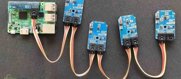
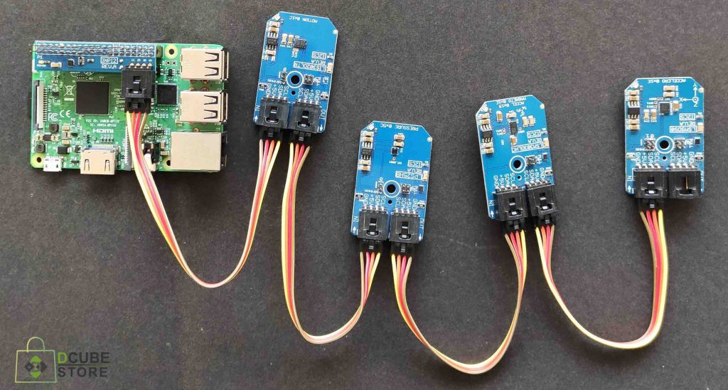
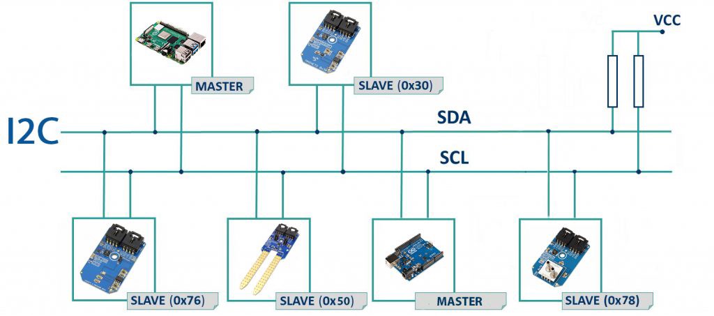 I2C multi-master and multi-slave Communication
There is no constant connection between master and slave, transmitting and receiving on the bus. It only depends on the direction of the data at the time. If the master decides to transmit the data to the slave then before sending any data, the master must first address the slave. Additionally, the power supply must be connected via a pull-up resistor. When the bus is idle, both the lines should be on high power.
Steps to transfer data between master and slave device:
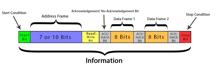 I2C frame
- The master sends a transmission signal to each connected slave by replacing the SDA channel from high voltage to low voltage and the SCL channel from high to low after replacing the SDA channel.
- The master sends the target slave address, which is compared with the addresses of all the slave devices connected to the SCL and SDL lines. Then all slaves compare the address with their own address. If the address matches any device, that device is selected and all the other devices are removed from the SCL and SDL lines and that slave(device) reverts an ACK bit that switches the SDA line low to one bit. If the address does not match its address, the Slave will leave the SDA line high.
- After that master sends the data frame or receives it. After the transmission of each data frame, the slave returns another ACK bit to the master to acknowledge the successful data transfer.
- To end the transmission of data the master sends the slave a stop signal by changing SCL high before shifting SDA high.
How Clock(SCL) works in I2C data transmission:
- All masters generate their own clocks on the SCL line to send messages to the I2C bus.
- Data is only acceptable throughout the clock?s high time cycle.
- Synchronization of the clock is carried out by connecting the I2C interface to the SCL wire, where the transition shifts from high to low.
- Once the clock of the device goes low it will keep the SCL line in low state until it reaches the clock?s high level.
- The low-to-high transition does not change the state of the SCL line if another clock is still in a low time cycle. The device with the longest low period often holds the SCL line low.
Transmission modes in I2C communication:
- Standard mode: 100Kbps
- Fast mode: 400Kbps
- High-Speed mode: 3.5Mbps
- Ultra-fast mode: 5Mbps
Synchronous or Asynchronous: Synchronous
Serial or Parallel: Serial
Advantages of I2C Communication:
- Efficient, because it allows multiple master multiple slave communication.
- Allows communication using two wires only.
- Uses ACK / NACK bit that confirms every data frame is successfully transmitted.
Disadvantages:
- I2C has a half-duplex interface.
- May become complex as the number of devices increases.
- It may become complex with increasing numbers of devices.
What is SPI Protocol?
SPI or Serial Peripheral Interface is a full-duplex synchronous serial communication protocol that is used for short-distance communications. The unique advantage of SPI is that the data can be transferred without interruption. A number of bits can be sent or received in a continuous stream.
Serial Peripheral Interface (SPI) is a master-slave style protocol that has a single master and multiple slave architecture. SPI is used to send data between the microcontroller(master) and peripheral devices(slaves) such as shift registers, sensors, etc. It uses a separate clock, data wires, and select lines to select the device which it wants to send data.
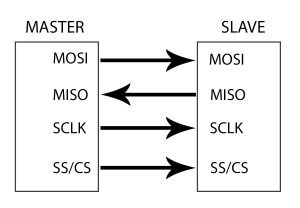
SPI Protocol consist of 4 wires:
 SPI Communication
- MOSI (Master-Out Slave-In) ? Master line to send the slave data.MISO
- (Master-In Slave-Out)? Slave line to send the master data.
- SCLK (Serial Clock) ? Line to send clock signal.
- SS/CS(Slave Select/Chip Select) ? Master?s line to choose the slave.
SPI is also a serial communication and in this data can be sent in a continuous stream.
History of SPI protocol:
Motorola developed the SPI interface in the mid-1980s and it has become a de-facto standard. Ideally suited for use of data stream applications. Secure Digital cards and liquid crystal displays (LCDs) are common applications.
How SPI works?
1. The communication is started by the master always. Next, the master arranges the clock using a frequency that is less than or equal to the maximum frequency allowed by the slave. Now, the master manages the transfer of data by producing the clock signal (SCLK).
2. The master then selects the desired slave for communication by switching the slave peripheral (SS) selection chip to a ?low? state and activating the specific slave whom the master wants to communicate by using the slave selection (SS).
3. The master sends data bit by bit to the MOSI slave by sending the MSB bit first. Slaves read bits when received.
4. If an appropriate response is required then the slave gives the master data one bit at a time along the MISO line by sending LSB bit first. As received the master reads the bits.
Operating Modes of SPI:
The master and slave really have to decide on certain protocols for synchronization. For those two clock characteristics, the Clock Polarity (CPOL or CKP) and the Clock Phase (CPHA) required.
The polarity of the clock determines the state of the clock. If CPOL is LOW, then master generates the clock, e.g. when Idle SCK is low state and switches to HIgh state during data transfer. Likewise, when CPOL is Up, SCK is HIGH in idle state and LOW in the active state.
The phase of the clock determines the clock transition, i.e. switching (LOW to HIGH) or switching (HIGH to LOW), when data is sent. If CPHA is 0, data is transferred to the rising clock edge. Data is transferred to the falling edge when CPHA is 1.
Depending on the values for clock polarity (CPOL) and clock phase (CPHA), there are 4 SPI modes: modes 0 to 4.
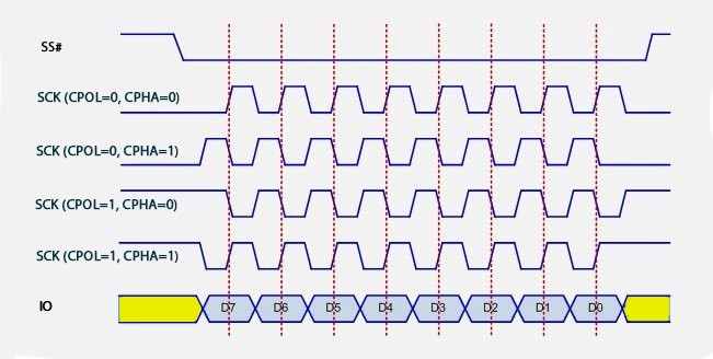
- Mode 0(CPOL = 0 and CPHA = 0):Mode 0 occurs when the clock polarity is LOW and the clock phase is 0. In mode 0, data transmission takes place on the rising edge of the clock.
- Mode 1(CPOL = 0 and CPHA = 1):Mode 1 occurs when the clock polarity is low and the clock phase is 1. In mode 1, data is transmitted with the falling end of the clock.
- Mode 2(CPOL = 1 and CPHA = 0):Mode 2 occurs when the clock polarity is HIGH and the clock phase is 0. In mode 2, data is transmitted as the clock edge increases.
- Mode 3(CPOL = 1 and CPHA = 1):Mode 3 occurs when the clock polarity is HIGH and the clock phase is 1. In mode 3, data is transmitted as the clock edge increases.
Synchronous or Asynchronous: Synchronous
Serial or Parallel: Serial
Advantages of SPI Communication:
- There is no start and stop bit, so data can be transferred continuously without interruption.
- SPI is a full-duplex communication protocol.
- It has high-speed data bus 10 MHz.
- Different MISO and MOSI lines, so that data can be sent and received simultaneously.
Disadvantages of SPI Communication:
- SPI uses four wires for communication.
- It supports only one master.
- An additional dedicated master pin for CS or SS is needed for each additional slave.
- No protocol is set for error detection.
- No acknowledgment mechanism is established and therefore data receipt is not confirmed.
How to choose between I2C and SPI?
I think you?ve got to learn some information from this post, but let me tell you a little difference that?s going to help you determine which one you need.
When to use the I2C protocol
- If you want accurate data transmission, as the acknowledgment mechanism is supported by I2C.
- I2C is required when two cables/pins want to communicate with multiple slaves. With SPI, multiple slaves require multiple Slave Select(SS) wires. Therefore, I2C is a better choice if you have a limited number of pins.
When to use the SPI protocol
- If you want to send data at a higher speed, SPI is a better choice.


)
)