
A state machine diagram is a behavior which specifies the sequence of states an object visits during its lifetime in response to events, together with its responses to those events.
State
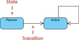
A state is a condition during the life of an object during which it satisfies some condition, performs some activity, or waits for some external event
Example:
Characteristics of State
- State represent the conditions of objects at certain points in time.
- Objects (or Systems) can be viewed as moving from state to state
- A point in the lifecycle of a model element that satisfies some condition, where some particular action is being performed or where some event is waited
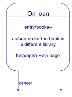
The Figure below shows a detailed description of a state. The state is extended with internal actions (do, help). In contrast to other actions, these actions can be interrupted. If ?cancel? happens, the do or help actions are interrupted. Internal actions are performed after the ?entry? section and are aborted when the state is left.
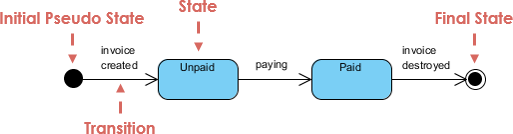
Initial and Final States
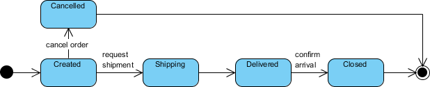
- The initial state of a state machine diagram, known as an initial pseudo-state, is indicated with a solid circle. A transition from this state will show the first real state
- The final state of a state machine diagram is shown as concentric circles. An open loop state machine represents an object that may terminate before the system terminates, while a closed loop state machine diagram does not have a final state; if it is the case, then the object lives until the entire system terminates.
Example:
Event
An event is the specification of a significant occurrence. For a state machine, an event is the occurrence of a stimulus that can trigger a state transition.
Transition
A transition is a relationship between two states indicating that an object in the first state will, when a specified set of events and conditions are satisfied, perform certain actions and enter the second state.
A transition has: Transition Components which includes (1) a source state (2) event trigger (3) an action (4) a target state
Self-Transition
A self-transition is a transition whose source and target states are the same
Action
An action is an executable, atomic (with reference to the state machine) computation. Actions may include operations, the creation or destruction of other objects, or the sending of signals to other objects (events)
Library Example
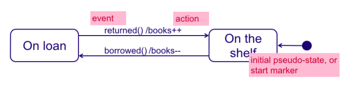
The Figure below shows a simple state machine diagram. The main components of such a diagram are:
- State: the example has two states: ?On loan? and ?On the shelf?.
- Initial state: this is the state in which the system starts.
- Transitions: transitions describe possible state changes. The diagram has two transitions: from ?On Loan? to ?On the shelf? and vice versa.
- Events: events are labelled on transitions. They represent the event performed on a transition. When moving from state ?On loan? to state ?On the shelf?, event ?returned()? is performed.
An actions are modifications of the state variables. In the example below, actions are specified on transitions. When the transition from ?On the shelf? to ?On loan? is taken, state variable books is decreased.
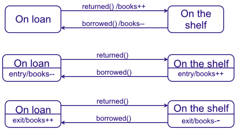
Actions can be specified on transitions, but also in states. In that case, one can specify whether the action must be performed when entering or leaving the state. In the Figure below shows these options.
- The first option shows the specification of actions when a transition is taken. The action is performed on the state change.
- The second option shows the specification of an action in a state. The ?entry? keyword indicates that the action must be performed when the state is entered.
- Finally, the third option shows how to specify that an action is taken on leaving a state. Note the ?exit? keyword.
Simple State Machine Diagram Notation
State Machine Diagram ? Advanced Concepts
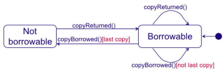
Constraints
It is possible to add constraints to transitions. Consider Figure below. Constraint ?[not last copy]? and ?[last copy]? are used to distinguish the two transitions with the event ?copyBorrowed()?. The semantics is that a transition is enabled when the constraint is true.
Substates
A simple state is one which has no substructure. A state which has substates (nested states) is called a composite state. Substates may be nested to any level. A nested state machine may have at most one initial state and one final state. Substates are used to simplify complex flat state machines by showing that some states are only possible within a particular context (the enclosing state).
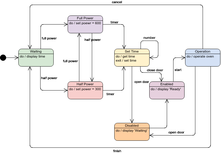
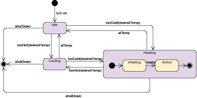
Substate Example ? Heater
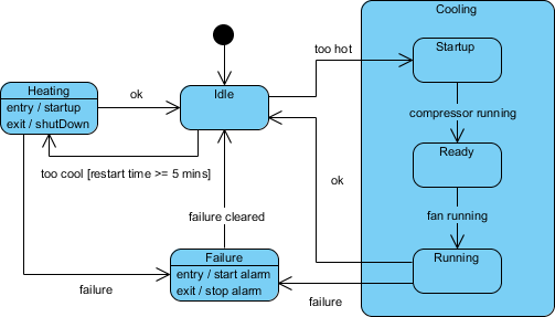
State Machine Diagrams are often used for deriving testing cases, here is a list of possible test ideas:
- Idle state receives Too Hot event
- Idle state receives Too Cool event
- Cooling/Startup state receives Compressor Running event
- Cooling/Ready state receives Fan Running event
- Cooling/Running state receives OK event
- Cooling/Running state receives Failure event
- Failure state receives Failure Cleared event
- Heating state receives OK event
- Heating state receives Failure event
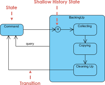
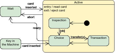
History States
Unless otherwise specified, when a transition enters a composite state, the action of the nested state machine starts over again at the initial state (unless the transition targets a substate directly). History states allow the state machine to re-enter the last substate that was active prior to leaving the composite state. An example of history state usage is presented in the figure below.
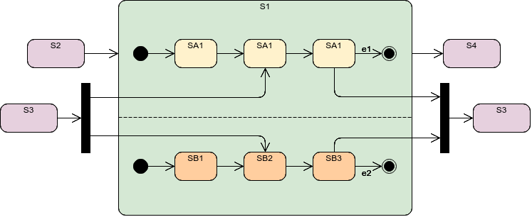
Concurrent State
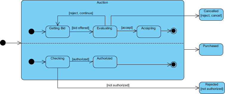
As mentioned above, states in state machine diagrams can be nested. Related states can be grouped together into a single composite state. Nesting states inside others is necessary when an activity involves concurrent sub-activities. The following state machine diagram models an auction with two concurrent substates: processing the bid and authorizing the payment limit.
Concurrent State Machine Diagram Example ? Auction Process
In this example, the state machine first entering the Auction requires a fork at the start into two separate start threads. Each substate has an exit state to mark the end of the thread. Unless there is an abnormal exit (Canceled or Rejected), the exit from the composite state occurs when both substates have exited.
Related Links
- What is Unified Modeling Language?
- Professional UML diagram tool
Do It Yourself State Diagram Examples with Visual Paradigm Online
- Free State Machine Diagram examples and templates editable in an online State Machine Diagram software: Visual Paradigm Online.
- Use the templates as a starting point to create your own State Machine Diagram.
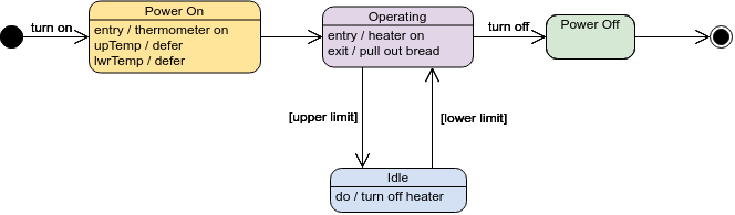
Oven
Digital Clock
Orthogonal State
Composite State
Heater
Toaster
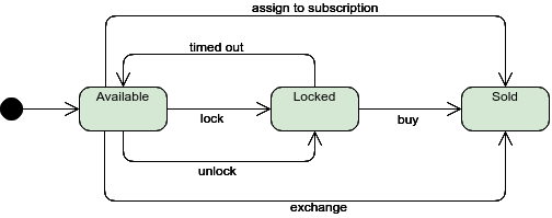
Ticket Selling System
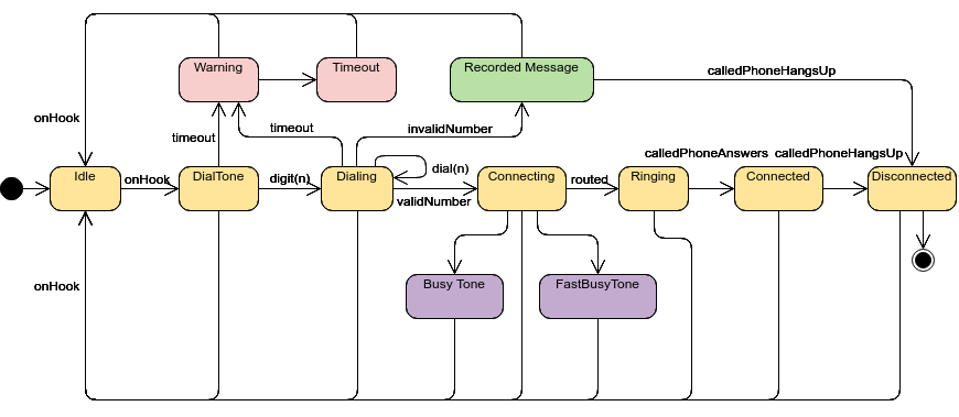
Phone
Free UML Software Tool
You?ve learned what a State Machine Diagram is and how to draw a State Machine Diagram. It?s time to draw a State Machine Diagram of your own. Get Visual Paradigm Community Edition, a free UML software, and create your own State Machine Diagram with the free State Machine Diagram tool. It?s easy-to-use and intuitive.
Free Download

