If you?ve bought yourself an old Beetle, Split, Bay, Karmann Ghia or even an aircooled Porche, the chances are you?re going to need to do a little bit of maintenance yourself.
The good news is that the type 1 upright engines are one of the easiest engines to work on. I?ve gone from having zero knowledge a few years back to being able to diagnose and fix most of the common problems myself, you can do it too!
For this article I?ll only be focusing on the top end of the engine as this is where the majority of DIY work can be done as a beginner. If you have a problem with the internals of your engine, I would recommend going to a specialist.
Engine layout
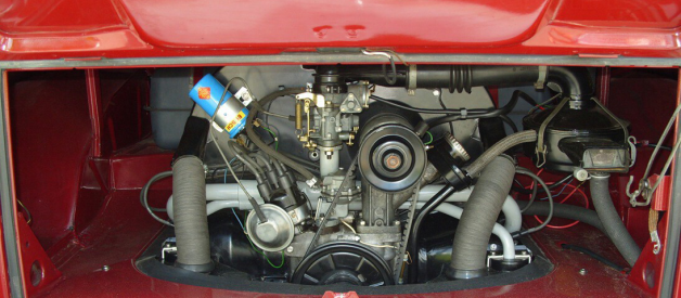
Here?s what a relatively stock type 1 engine should look like when you open your rear hatch. Beetle, bus or Ghia you should see pretty much the same thing.
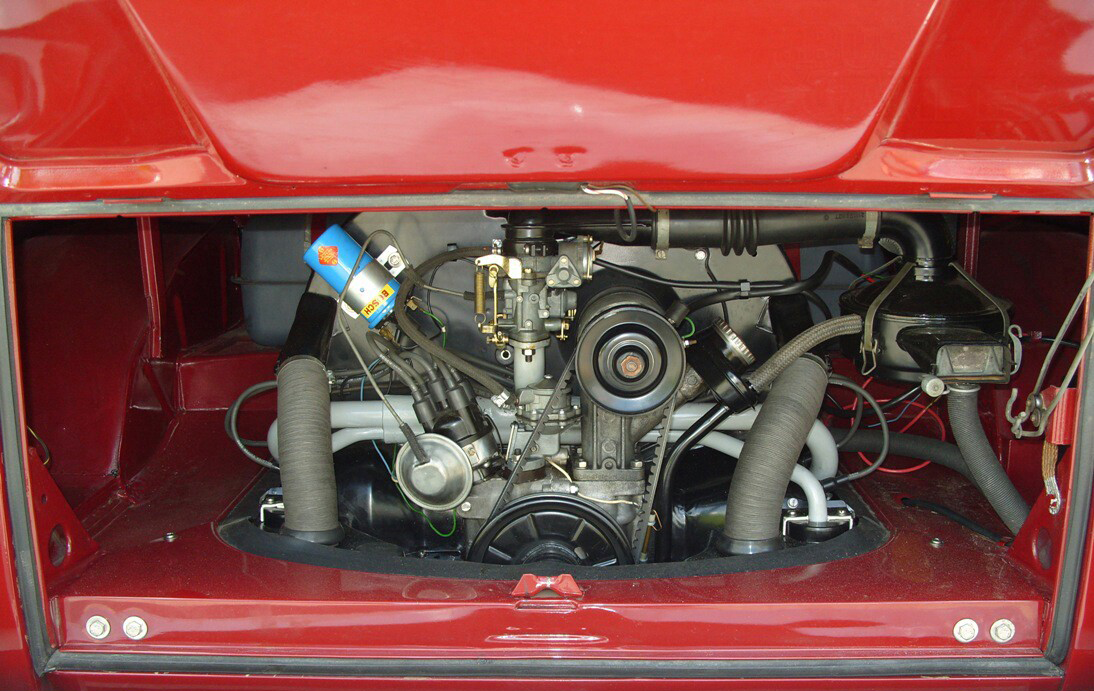 An (almost) stock upright 1600 type 1 engine from an early bay window bus BusandCamper.com
The chances are your engine will no longer be entirely stock, even if parts have been changed like for like, an original engine will be at least 40 years old and previous owners of your vehicle would have all put their own stamp and tastes on it over the years.
Don?t worry if your engine looks slightly different, we?ll cover some common changes below.
Engine basics
Before we get into the details of each component, you?ll need a basic understanding of how a combustion engine works.
This animation shows a type 1 engine in operation. This type of engine is known as a ?flat four? engine because it has four horizontal cylinders, but the principles for all combustion engines are the same. The suck, the squeeze, the bang and the blow.
 An animated image of an aircooled flat four engine
The suck
An air and fuel mixture is sucked into a cylinder.
The squeeze
A piston, which fits snugly inside the cylinder, heavily compresses the air and fuel mixture.
The bang
At the point where the piston has compressed the air and fuel mixture as much as possible the air and fuel mixture is ignited, causing a mini explosion, forcing the piston backwards.
The blow
In the same way that igniting something outside of an engine would cause smoke, the combusted air and fuel mixture has filled the cylinder with hot gasses known as exhaust. In the next cycle of the piston in the cylinder, it pushes these gases out of a valve into the exhaust system, leading to the exhaust pipe on your car.
Working in sync
This happens to every cylinder in turn hundreds of times a minute, so the engine needs to be in sync. If the spark plug (the bang) was to fire before the piston had finished compressing the air and fuel mixture (the squeeze) then the explosion would be much smaller and the engine would have significantly less power. This synchronisation of the spark to the compression is called timing.
Which part is which? (and what they do)
For the majority of this article we?ll be referring to this annotated image.
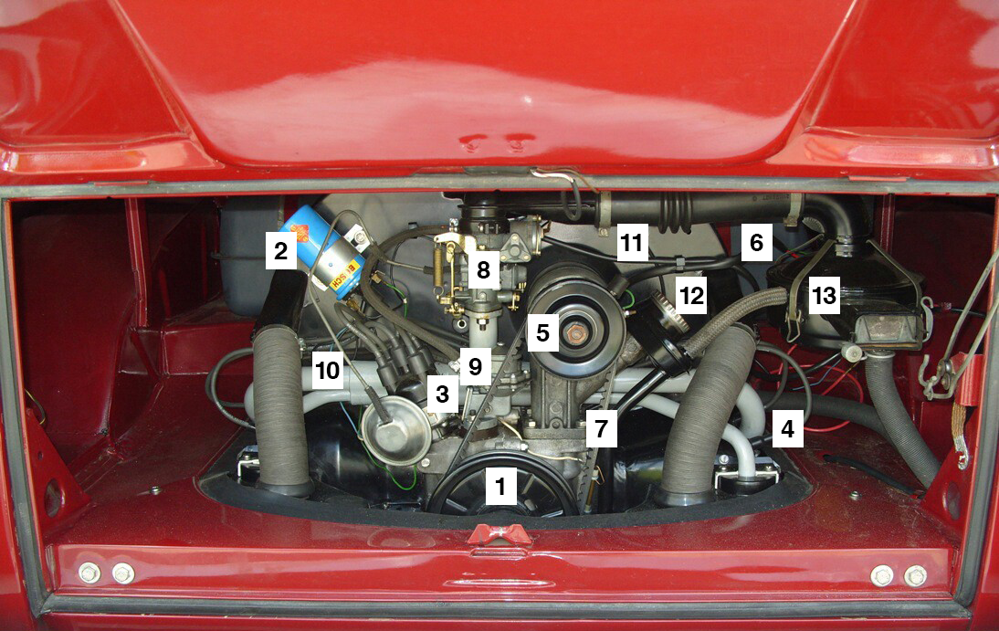 An annotated image of the stock type 1 engine
1. Crank shaft pulley
The crank shaft pulley is our main visible link to engine turning on the inside. On the other side of this spinning disc there is something called a crank shaft which drives the pistons inside the engine. Right now, all we?ll only be talking about the pulley itself.
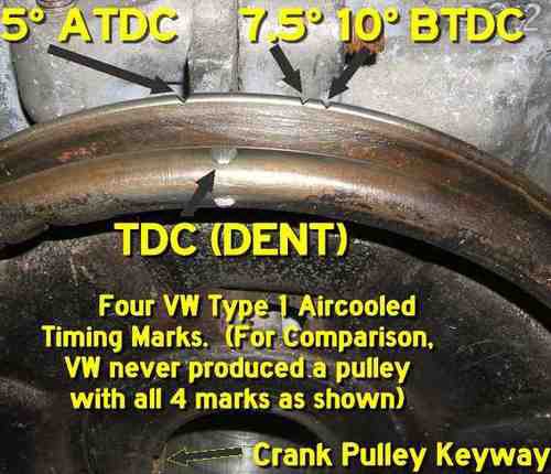
Whether you have a stock pulley or an aftermarket one you will see a few marks on it. The main mark, shown below as a dent (bit will be marked TDC or 0 on an after market pulley) tells us where the engine is in its cycle. It?s almost like being able to see through the engine case to find out what position the pistons are in. Top Dead Centre (TDC) is the furthest point in the piston?s travel for cyclinders 1 and 3, Bottom Dead Centre (BDC) is the same for cyclinders 2 and 4 and is 180 degrees opposite of TDC on the pulley.
The other marks on the pulley are timing marks. On a stock pulley these will be notches cut out of the back side. These marks represent certain degree intervals around the pulley, the first one to the right of TDC is 7.5 BTDC, meaning 7.5 degrees before top dead centre.
These are used as timing marks because, depending on your distributor (3) this is the point where you want the spark plug to fire, just before TDC.
 An annotated stock crank shaft pulley
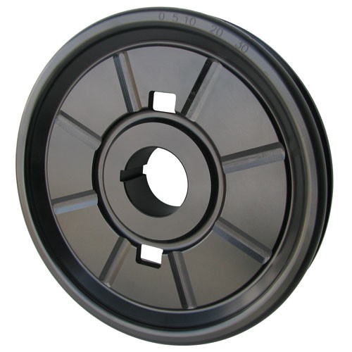 An after market pulley with degrees marked on it
2. Ignition coil
The coil provides the electrical power for the spark plugs. It transforms the low 12 volts of the battery up to 40,000 volts that are needed to ignite the air and fuel mixture.
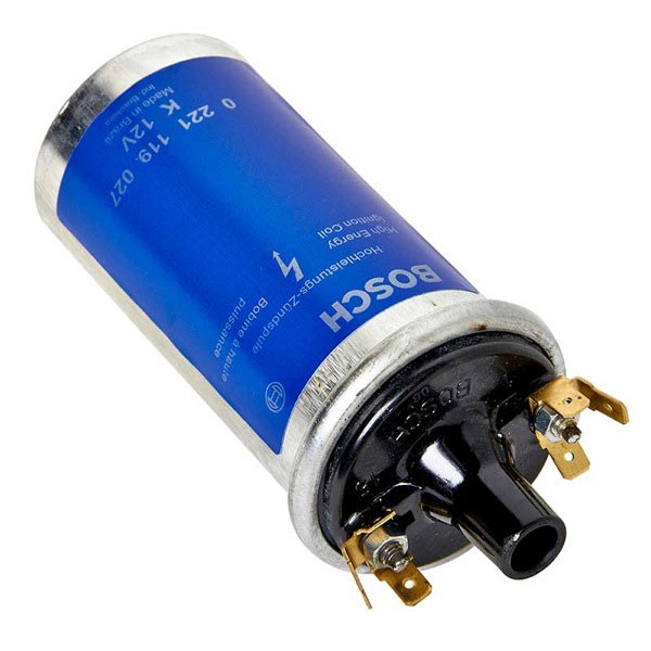
The output of the coil is a small HT (High tension) lead connecting to the distributor (3).
3. Distributor
The distributor takes the the power from the coil, and distributes it into each spark plug (4) through and additional four HT leads.
There?s a few different types of distributor, the most common are SVDA (Single Vacuum Dual Advance) and the ?009? (which is stamped on the side).
An SVDA uses what?s called a vacuum advance, you can tell if you have vacuum advance if it has a component that looks like a bit like a brass pork-pie hat on the side of the distributor, connecting to a hose leading to your carburettor (9).
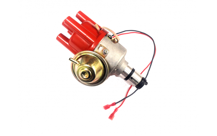 An SVDA distributor with electronic ignition
A ?009? distributor does not normally have vacuum advance so won?t be connected to your carburettor. You should take some time to read about the differences between vacuum and mechanical advance.
The distributor cap has 5 plugs to attach HT leads to. The plug in the centre will be connected to the coil (2) using the short lead. This is where the power comes in. The remaining four are outputs and will each be connected to the spark plug (4) for each cylinder.
The firing order of a VW type 1 engine is 1?4?3?2. This means the engine cycle (Suck, squeeze, bang, blow) will start on cylinder 1, then move to cylinder 4, then 3, then 2.
With an SVDA distributor, the HT lead for cylinder 1 should be connected to the distributor cap in the 5 o?clock position, cylinder 4 in the 7 o?clock position, cylinder 3 in the 11 o?clock position and cylinder 2 in the 1 o?clock position.
A common mistake is to try and mirror the leads on the cap to the position of the cylinders in the engine bay, but due to the firing order of this engine that is not the case.
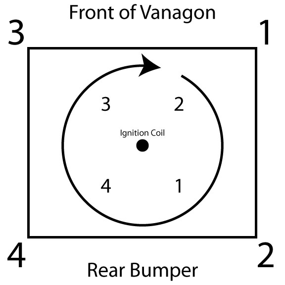 The cylinder positon (outside) and where they link to the distributor cap (inside).
If you have a 009 distributor they have a slightly different orientation. Everything is in the same order, but moved one position counter clockwise with cylinder 1 in the 1 o?clock position.
What?s inside a distributor?
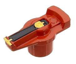
Inside the distributor there are a few important parts. The first thing you?ll see under the cap is the rotor. The rotor spins in a clockwise direction as the engine turns over. As it spins it distributes the power to each HT lead in turn.
Underneath that you will either have what are called points or an electronic ignition.
A distributor with points will look like the image below inside. Points manually open and close as the distributor turns allowing the current to travel through them. If you have points, setting the gap between the points will be part of your yearly maintenance routine.
 A distributor with points and condenser (the cylinder on the side of the unit)
A distributor with an electronic ignition will have the points swapped out for something that looks like this.
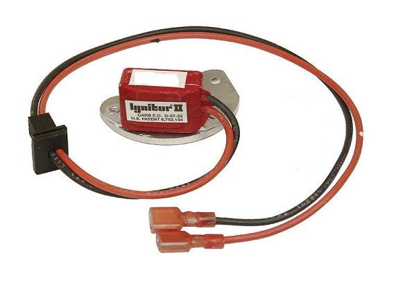 An example of an electronic ignition
Having an electronic ignition is a great addition to your distributor, it?s one less thing to maintain and gives you a much more reliable starting experience.
However electronic ignition components have been known to occasionally fail. It?s worth keeping your old points and condenser in your vehicle incase you get stranded. I personally keep a back up distributor in my bus just in case.
4. Spark plugs
As mentioned in the distributor section, the spark plug delivers the spark that causes the combustion in the cylinder.
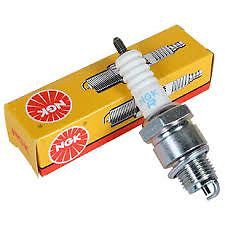 An example NGK spark plug, make sure you have the right ones for your engine
You should check your spark plugs every year. The condition of the spark plugs can tell you a lot about how your engine is running, not to mention make a world of difference to the performance of the engine.
If you are having trouble with misfiring, timing your engine or acceleration, before you do anything else clean or replace your spark plugs. A whole set only costs 10?15 so it?s worth chnaging them regardless and keeping your old set as a back up.
When replacing or renewing your plugs you will need to check the size of what?s called the electrode gap. To ignite the air and fuel mixture in the cylinder that electricity is no good to us inside the plug.
The spark plug is designed for the electricity to arc (electric current flowing through an air gap between conductors) from the centre electrode (a small nub at the end of the plug) to the side electrode (a piece of metal that is bent over at 90 degrees over the centre electrode).
If the gap is too large the electricity won?t be able to arc and there will be no spark to ignite the fuel mixture.
The gap can be checked and adjusted using some special but inexpensive tools, for a type 1 engine set it to 0.6mm.
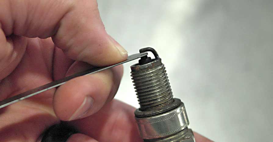 Measuring a spark plug gap with a feeler gauge
5. Generator / Alternator
The power that?s supplying your ignition coil (2), in fact anything electrical, is coming from the battery. Like any battery you might find in your house, a car battery holds only a limited amount of power, without being recharged you will find it will run down very quickly.
The generator, or a more modern alternator uses the energy of the engine to re-charge the battery. It?s connected to the Crank shaft pulley (1) with with the Fan belt (7), so as the engine spins, so does the generator.
When the generator spins it creates electricity. A generator is connected to a voltage regulator (6) which then connects to the battery to charge it. An alternator has an internal voltage regulator so you?ll only have one of these if you have an original generator.
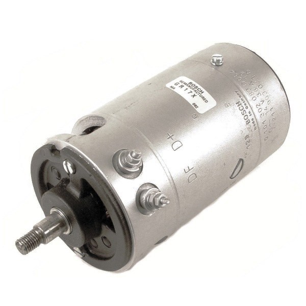 An original style generator
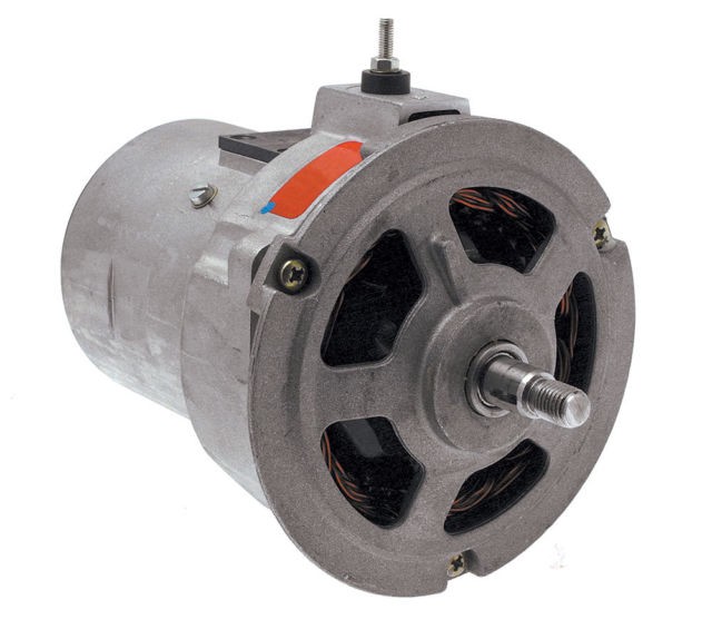 An upgraded alternator, note the differences in design
An alternator upgrade will generate more power, this means the battery can be charged in less time and as the vehicle will have more electricity available, you?ll find your headlights may shine just that little bit brighter.
Upgrading to a higher spec alternator that can collect more power than the battery needs will be an advantage if you own a camper. Often campers owners set up and additional leisure battery to power a few home comforts when they are away from an electrical hookup.
Keeping the engine cool
The spinning generator or alternator has a second job to do on an aircooled engine. The rear of it is attached to a fan which cools the engine inside the fan housing. If your fan belt breaks your generator will stop turning, which more importantly means your fan will stop spinning.
If you see the red generator warning light (G) appear on your speedo you should pull over immediately. While you can often get home without a functioning generator, you won?t make it without fanbelt.
6. Voltage regulator
As mentioned in the Generator (5) section, you only need an external voltage regulator if you have a generator. They are normally located at the back right of the engine bay on a T2 bus or depending on the year, directly on top of the generator on a beetle.
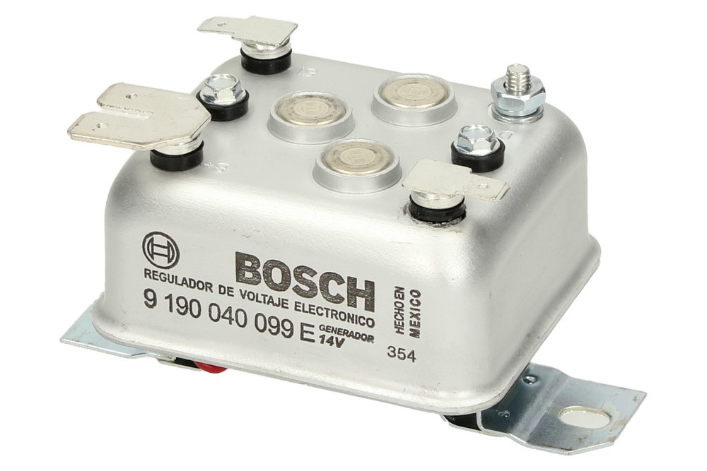 A voltage regulator
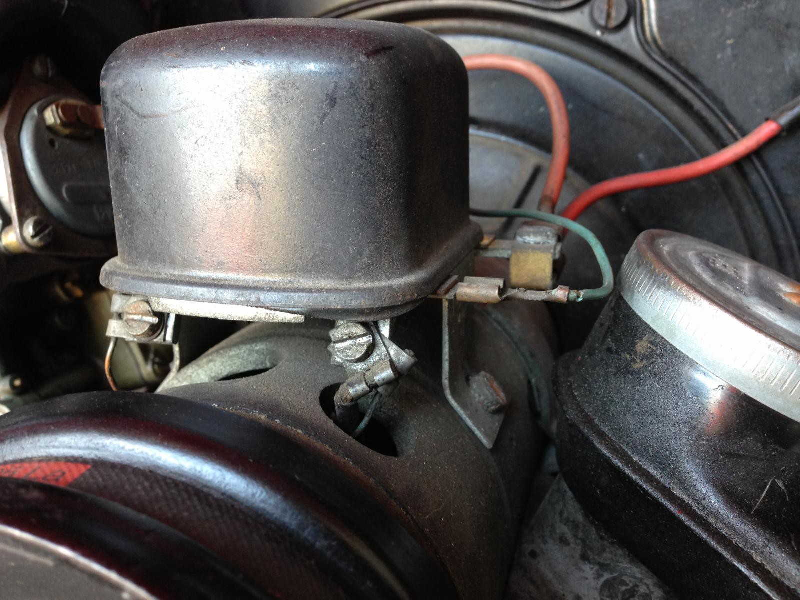 A voltage regulator mounted directly to a generator
A regulator is a little hard to explain, however you should consider it somewhat of a translator between the generator and the battery. It monitors the voltage created by the generator and also the charge of the battery. Once the battery is charged the regulator cuts off the power being created by the generator so it doesn?t overcharge.
If you?re having charging issues a broken regulator is more often the culprit than the generator itself.
7. Fanbelt
The fanbelt links the Crank shaft pulley (1) and the Generator (5). This causes the generator to spin, which in turn spins the fan on the other side of the generator.
The fanbelt should be tight enough that you can twist it about 90 degrees with your thumb and finger.
To make any changes to the fan belt tension you will need to remove the front of the generator pulley. First, find a notch on the rear side of the pulley and insert a flat head screwdriver into it. As you turn the generator, there will be a point where the pulley will stop turning because to the screwdriver. Once this is locked in you can use the resistance to undo the nut on the front of the generator.
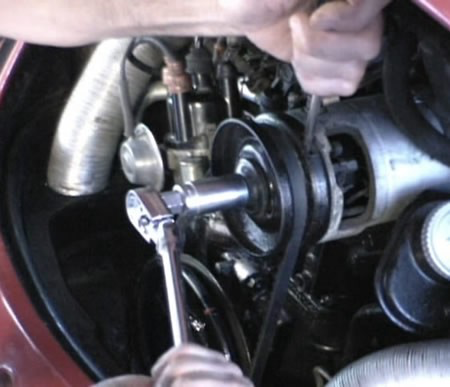 A generator pulley being removed
If the fanbelt needs to be tightened or loosened this is done by moving shims, small washer like pieces of metal to the inside or outside of the generator pulley.
Although this seems odd it?s just a simple case of adjusting where the belt sits on the pulley. The more shims there are on the outside, the closer the pulley halves butt together. This means the belt is sitting higher up the pulley, causing it to be tighter.
There should always be 10 shims present, if you need to remove some from the inside they should be places on the outside.
 Shims to tighten or loosen your fanbelt
Just Kampers have a handy video you can watch on how to change your fanbelt.
8. Carburettor
The carburettor is responsible for delivering the air and fuel mixture to the cylinders. It takes fuel from the fuel pump (9), sucks in air and sends it down the inlet manifold (10).
Controlling the air and fuel mixture
The air and fuel mixture ratio is controlled by a mixture screw on the carburettor itself. This allows you to dial in a leaner (less fuel) or richer (more fuel) mix to the engine.
Depending on your experience with carbs, unless you have a problem that?s causing you real issues right now, for example not being able to drive your vehicle at all, I would suggest leaving well alone and get it set up by a professional as part of a service.
The throttle linkage
The accelerator cable travels from the accelerator pedal and pokes out a small hole in the fan housing just below the carburettor. It?s attached to the throttle section of the carb and controls the amount of fuel and air that is delivered to the engine.
When you put your foot down, the cable pulls the throttle open, the more you put your foot down the more fuel goes into the carb. When you take your foot off the pedal, to avoid the throttle getting stuck in the open position, a spring called the return spring will reset the throttle to it?s starting position.
If you find your engine remains to rev after you?ve backed off of the accelerator this can mean the throttle has not been able to return, and is potentially stuck open. This could be down to a frayed cable that?s getting stuck somewhere between the pedal and the carb, a gunked up throttle linkage on the carb or a return spring that?s lost it?s tension.
Controlling the engine idle speed
The throttle linkage will also house a screw to set the engine?s idle speed. It sounds obvious but this is the number of revolutions per minute (rpm) that the engine will complete when the car is stationary without the accelerator applied. An average idle speed for an aircooled VW is 8?900 rpm but it?s dependant on a few factors.
Choke and fast idle
When the engine is cold, it may temporarily need a richer fuel mixture to get going. This is handled by something called a choke.
The choke temporarily closes or part closes the the air intake into the carburettor forcing a richer fuel mixture. Over a few minutes the choke will open up to it?s normal operating position.
Along with this, the engine can be put into ?fast idle? by pressing the accelerator all the way down to the floor before turning on the ignition, this is so the rpm is increased while the engine is warming up. The fast idle can be adjusted independently with a separate idle screw on the carburettor.
Single, progressive or dual carburettors
I?ve tried not be specific about where the parts of the carb are located, this is because many owners will have swapped their carb and these locations will vary.
The stock carb is usually a ?Solex 34 pict 3?, but your engine may have had a performance upgrade to a ?progressive? single carb or perhaps more common, a dual carb set up.These are all pictured below, it?s important you are able to identify and research your own carburettor set up as even the same model can have variations.
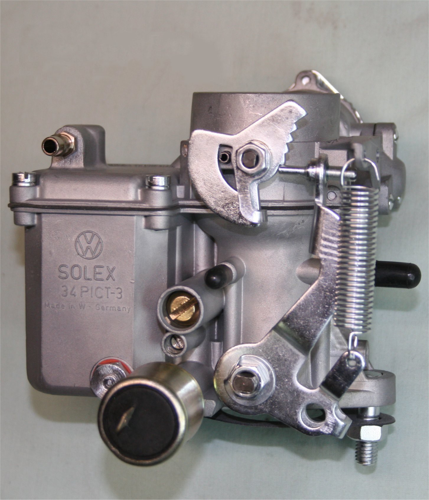 Solex 34 pict 3 stock carb
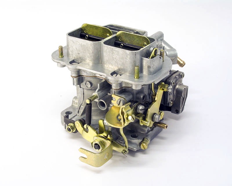 A Weber 32/36 progressive carb
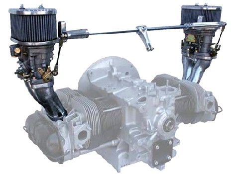 A dual carb setup with Weber ICT?s
9. Fuel pump
The fuel pump sits between the fuel line coming from the petrol tank and the carburettor (8). Fuel pumps on type 1 engines are relatively simple mechanical devices that piggy back on the rotation of the engine to pump fuel to the carburettor to the required pressure.
If you look at the engine animation below, follow the stem of the distributor (3) almost all the way down to the crank shaft pulley (1) you will see a small rod called a push rod bouncing up and down. This relationship with the engine rotation is important as the faster the engine is going, the more fuel needs to be pumped to the carburettor.

If you have dual carbs you may also have a fuel pressure limiter between the pump and the carbs, this is to make sure that the fuel pressure does not exceed the maximum amount the carburettor can handle.
10. Intake manifold
The intake manifold is the pipe structure in the centre of your engine. It takes the air and fuel mixture down the central pipe under your single carburettor, splits into the left and right side of the engine and delivers fuel to each cylinder through the thicker pipe.
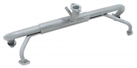 A stock single port intake manifold
Heat riser pipes
When looking at your intake manifold you will notice a thinner pipe on either side of the manifold which doesn?t go directly into the engine, but into the tinwear near the large air hoses. These are called heat riser pipes.
Heat riser pipes are not actually connected to the main pipes in the inlet manifold, they are connected to the exhaust system.
On a single carb engine the air and fuel mixture getting sucked down the intake manifold can cause the fuel to freeze up and turn to ice. This is called ?carb icing? and will cause the engine to stutter as it is starved of fuel. It?s pretty easy to diagnose, if you have a carb icing problem you will actually be able to see the ice forming or the manifold turning white / blue underneath the carb.
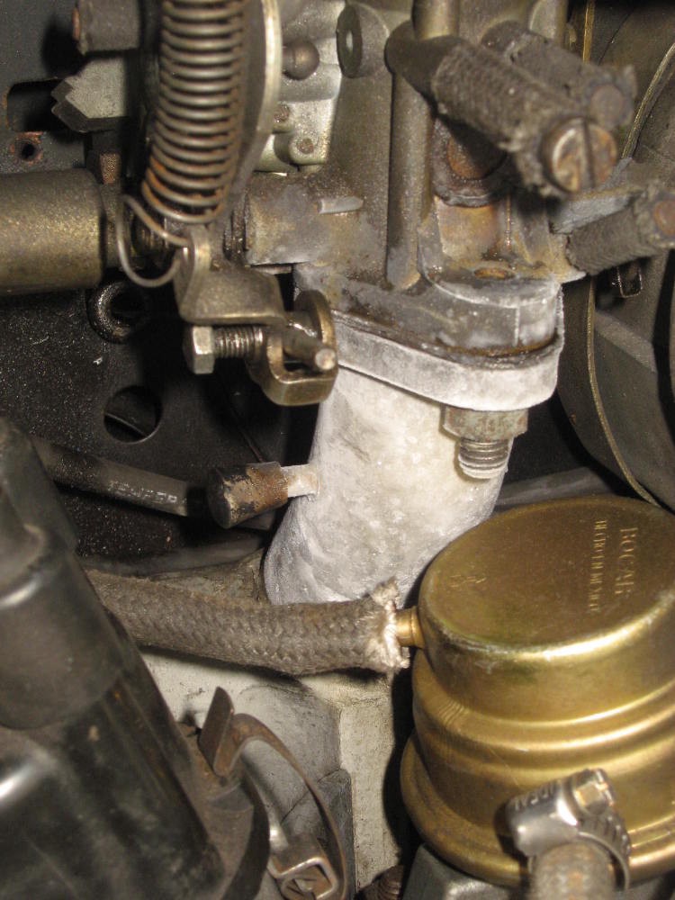 An intake manifold suffering from carb icing
To counter this, heat riser pipes take the heat of the exhaust and use it to warm up the entire manifold so the ice cannot form.
As the heat risers have a constant flow of exhaust they can get clogged with soot over the years and need to be cleaned out. Needless to say, a clogged heat riser is one of the main causes of carb icing.
Intake manifolds with dual carbs
If you have a dual carb set up, your inlet manifold will go straight from each carb, directly into the cylinder. Because they are comparatively so short, a dual carb set up should never suffer from carb icing.
11. Fan shroud
As mentioned in the generator (5) section, the back of the generator is connected to a fan. This is bolted to a tin shroud which sits over the back of the engine.
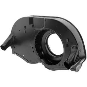 An fan shroud
As the fan spins, the air is distributed within the fan shroud and cools the engine, specifically the oil cooler.
The oil cooler is a large tower like component that sits under the shroud at the back left of the engine. These engines are air-cooled, but primarily the air is used to cool the oil. The cooler the oil, the cooler the engine will run.
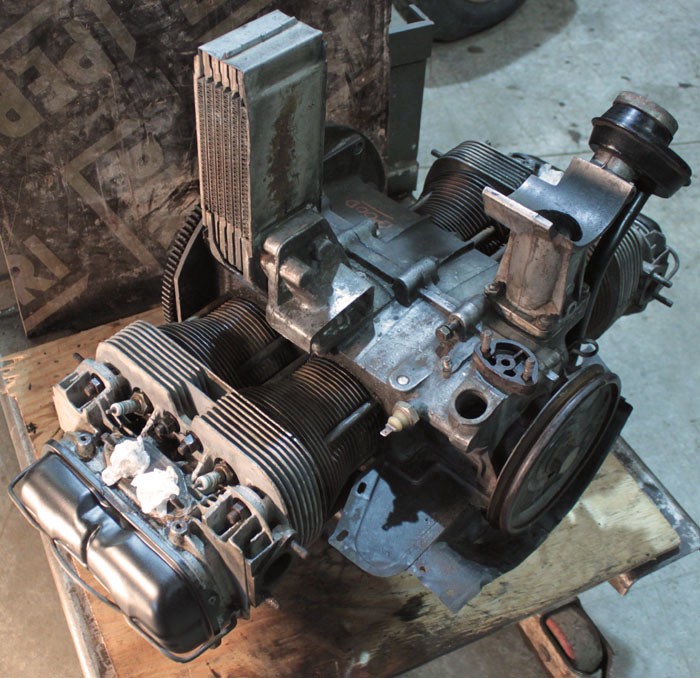 An engine block with the fan shroud removed, the oil cooler is the tower-like component at the top of the image
12. Oil filler
There?s not a huge amount to say about the oil filler, this is where you fill up your engine oil. I use Morris Golden Film SAE 30 oil in my T2 and tend to do an oil change every year or so.
Attached to the oil filler is a breather pipe. The breather allows the engine to vent excess pressure if and when required. This pipe should be connected to the air filter (13).
13. Air filter
On a stock bus engine, the air filter sits on a pedestal on the right hand side of the engine, connected to the top of the carburettor with a large plastic pipe. There?s a few variations of the air filter on different vehicles over different years, but if it?s made of black plastic it?s probably stock.
The air filter?s job is self explanatory. As we know, the carburettor sucks in air to create the air and fuel mixture. The air around the engine will be not be clean, even the smallest particles of dust getting through to the inside of carburettor would eventually block the flow of fuel and cause the engine to stutter or run rough.
The air filter itself, simply by doing it?s job will also get blocked up. If the air filter is blocked then the carburettor?s ability to suck in air will be limited.
Regardless of the type, you should check and clean your filter once a year.
Oil bath
This stock set up uses an oil bath underneath the filter. This is not a bath to collect excess oil as often thought, but in fact a way of cleaning the air by trapping particles in the oil itself.
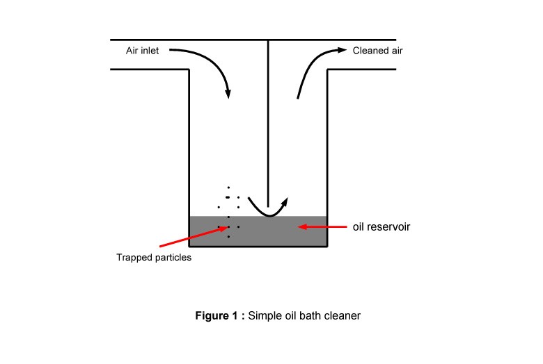 An example of an oil bath air cleaner
Pancake filter
If you don?t have an oil bath, don?t be surprised. The majority of engines I?ve seen have swapped out the stock air filter / oil bath setup for a pancake filter.
The pancake filter sits directly on top of the carburettor and the breather pipe from the oil filler (12) attaches to the underneath.
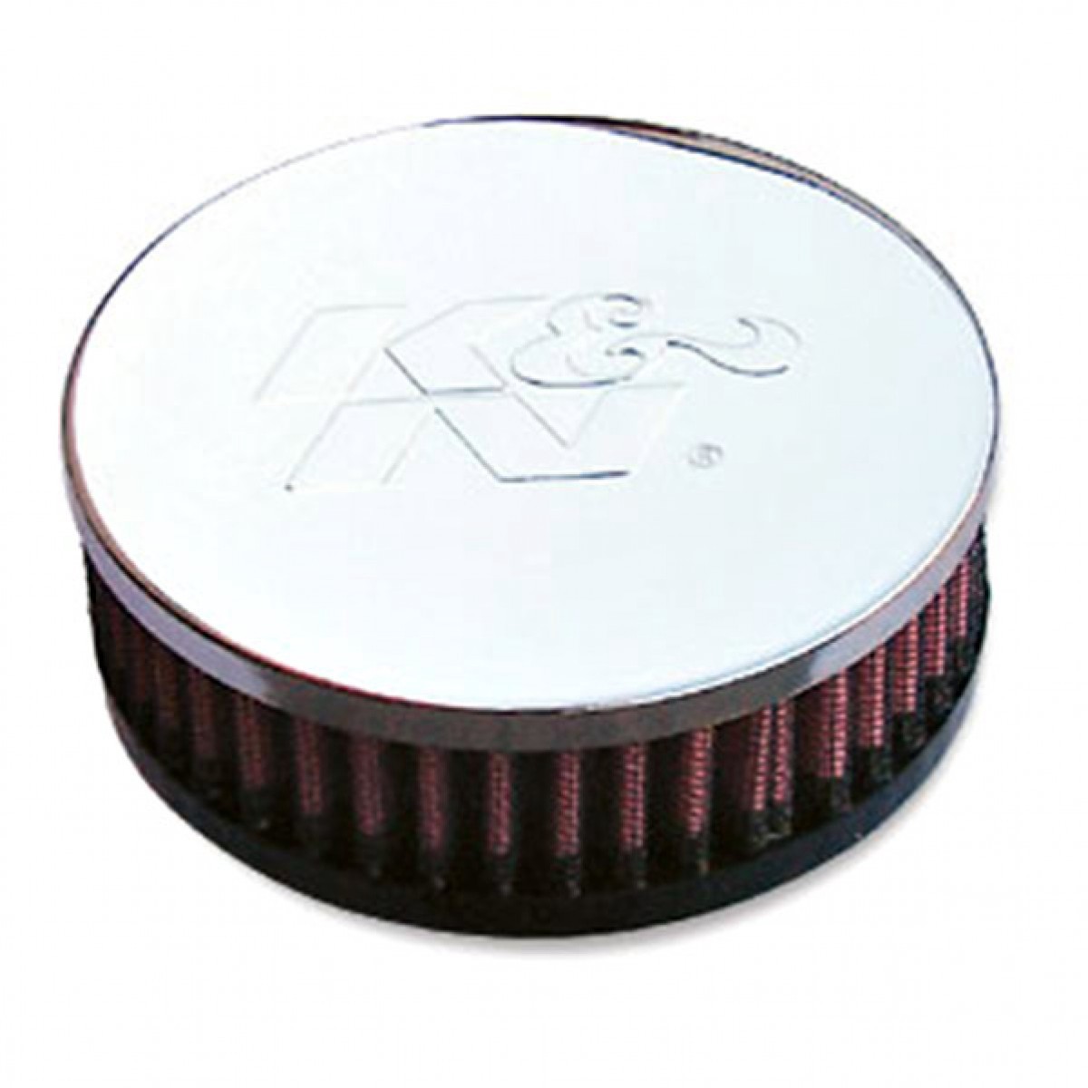 An example of a K&N pancake filter
You can do it!
So now you have a better idea of how the engine works and what each component does, you?re well on your way to being able to perform many of the tasks you?ll need to maintain your engine, or get yourself out of trouble when you need it.
Have fun 🙂

