I just want to reiterate what?s said here:
Understanding LSTM Networks
Posted on August 27, 2015 Humans don’t start their thinking from scratch every second. As you read this essay, you?
colah.github.io
I?m not better at explaining LSTM, I want to write this down as a way to remember it myself. I think the above blog post written by Christopher Olah is the best LSTM material you would find. Please visit the original link if you want to learn LSTM. (But I did create some nice diagrams.)
Although we don?t know how brain functions yet, we have the feeling that it must have a logic unit and a memory unit. We make decisions by reasoning and by experience. So do computers, we have the logic units, CPUs and GPUs and we also have memories.
But when you look at a neural network, it functions like a black box. You feed in some inputs from one side, you receive some outputs from the other side. The decision it makes is mostly based on the current inputs.
I think it?s unfair to say that neural network has no memory at all. After all, those learnt weights are some kind of memory of the training data. But this memory is more static. Sometimes we want to remember an input for later use. There are many examples of such a situation, such as the stock market. To make a good investment judgement, we have to at least look at the stock data from a time window.
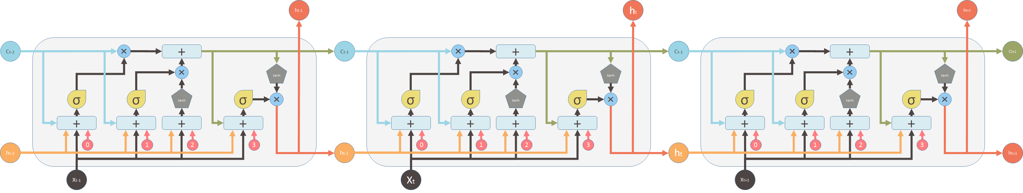
The naive way to let neural network accept a time series data is connecting several neural networks together. Each of the neural networks handles one time step. Instead of feeding the data at each individual time step, you provide data at all time steps within a window, or a context, to the neural network.
A lot of times, you need to process data that has periodic patterns. As a silly example, suppose you want to predict christmas tree sales. This is a very seasonal thing and likely to peak only once a year. So a good strategy to predict christmas tree sale is looking at the data from exactly a year back. For this kind of problems, you either need to have a big context to include ancient data points, or you have a good memory. You know what data is valuable to remember for later use and what needs to be forgotten when it is useless.
Theoretically the naively connected neural network, so called recurrent neural network, can work. But in practice, it suffers from two problems: vanishing gradient and exploding gradient, which make it unusable.
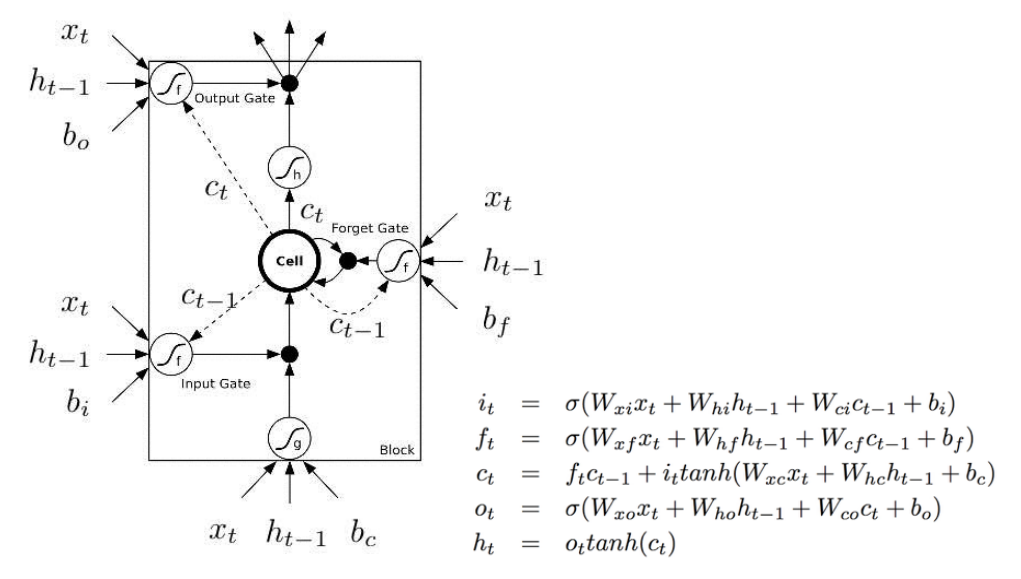
Then later, LSTM (long short term memory) was invented to solve this issue by explicitly introducing a memory unit, called the cell into the network. This is the diagram of a LSTM building block.
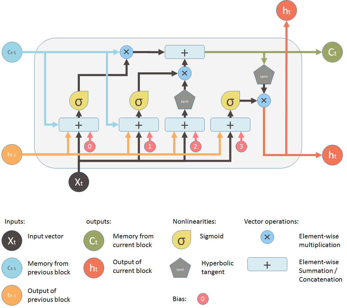
At a first sight, this looks intimidating. Let?s ignore the internals, but only look at the inputs and outputs of the unit. The network takes three inputs. X_t is the input of the current time step. h_t-1 is the output from the previous LSTM unit and C_t-1 is the ?memory? of the previous unit, which I think is the most important input. As for outputs, h_t is the output of the current network. C_t is the memory of the current unit.
Therefore, this single unit makes decision by considering the current input, previous output and previous memory. And it generates a new output and alters its memory.
The way its internal memory C_t changes is pretty similar to piping water through a pipe. Assuming the memory is water, it flows into a pipe. You want to change this memory flow along the way and this change is controlled by two valves.

The first valve is called the forget valve. If you shut it, no old memory will be kept. If you fully open this valve, all old memory will pass through.

The second valve is the new memory valve. New memory will come in through a T shaped joint like above and merge with the old memory. Exactly how much new memory should come in is controlled by the second valve.
On the LSTM diagram, the top ?pipe? is the memory pipe. The input is the old memory (a vector). The first cross ? it passes through is the forget valve. It is actually an element-wise multiplication operation. So if you multiply the old memory C_t-1 with a vector that is close to 0, that means you want to forget most of the old memory. You let the old memory goes through, if your forget valve equals 1.
Then the second operation the memory flow will go through is this + operator. This operator means piece-wise summation. It resembles the T shape joint pipe. New memory and the old memory will merge by this operation. How much new memory should be added to the old memory is controlled by another valve, the ? below the + sign.
After these two operations, you have the old memory C_t-1 changed to the new memory C_t.
Now lets look at the valves. The first one is called the forget valve. It is controlled by a simple one layer neural network. The inputs of the neural network is h_t-1, the output of the previous LSTM block, X_t, the input for the current LSTM block, C_t-1, the memory of the previous block and finally a bias vector b_0. This neural network has a sigmoid function as activation, and it?s output vector is the forget valve, which will applied to the old memory C_t-1 by element-wise multiplication.
Now the second valve is called the new memory valve. Again, it is a one layer simple neural network that takes the same inputs as the forget valve. This valve controls how much the new memory should influence the old memory.
The new memory itself, however is generated by another neural network. It is also a one layer network, but uses tanh as the activation function. The output of this network will element-wise multiple the new memory valve, and add to the old memory to form the new memory.
These two ? signs are the forget valve and the new memory valve.
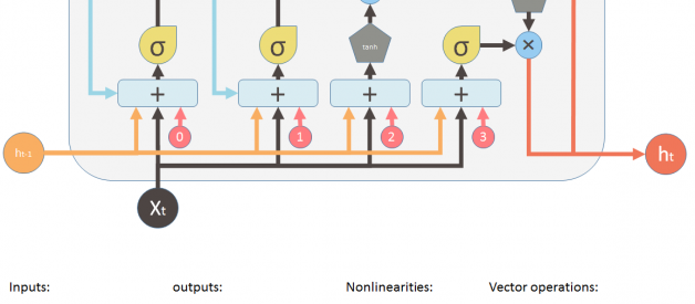
And finally, we need to generate the output for this LSTM unit. This step has an output valve that is controlled by the new memory, the previous output h_t-1, the input X_t and a bias vector. This valve controls how much new memory should output to the next LSTM unit.
The above diagram is inspired by Christopher?s blog post. But most of the time, you will see a diagram like below. The major difference between the two variations is that the following diagram doesn?t treat the memory unit C as an input to the unit. Instead, it treats it as an internal thing ?Cell?.
I like the Christopher?s diagram, in that it explicitly shows how this memory C gets passed from the previous unit to the next. But in the following image, you can?t easily see that C_t-1 is actually from the previous unit. and C_t is part of the output.
The second reason I don?t like the following diagram is that the computation you perform within the unit should be ordered, but you can?t see it clearly from the following diagram. For example to calculate the output of this unit, you need to have C_t, the new memory ready. Therefore, the first step should be evaluating C_t.
The following diagram tries to represent this ?delay? or ?order? with dash lines and solid lines (there are errors in this picture). Dash lines means the old memory, which is available at the beginning. Some solid lines means the new memory. Operations require the new memory have to wait until C_t is available.
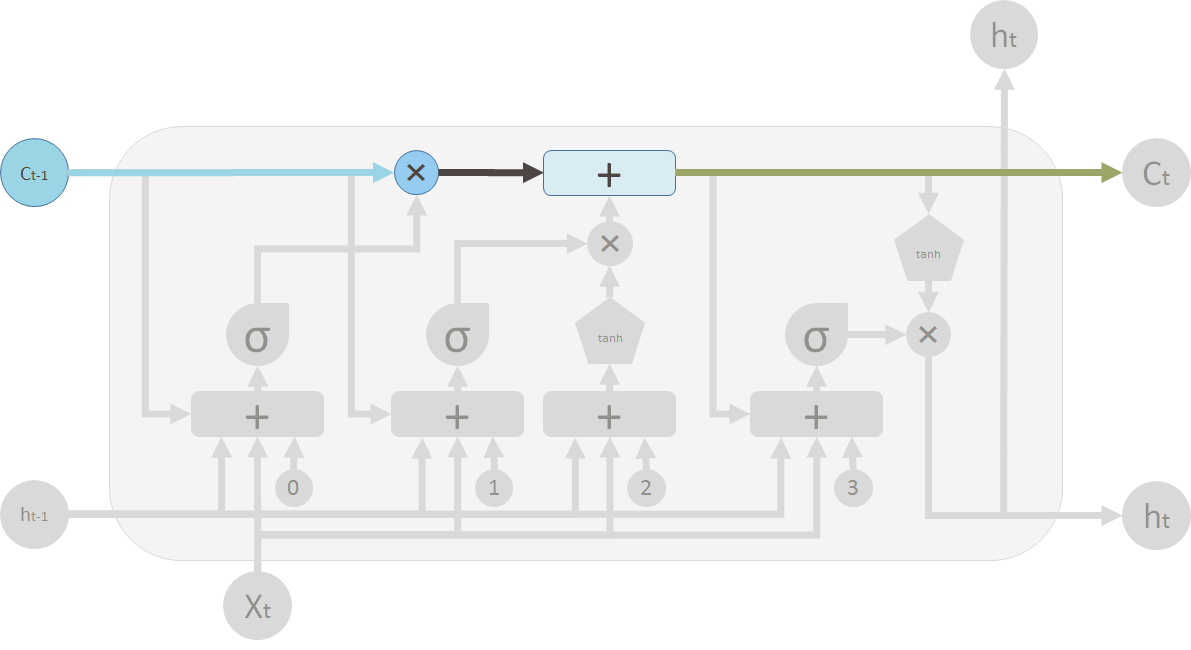
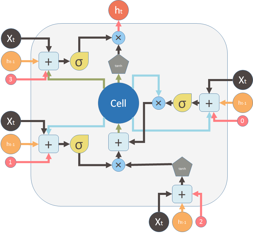
But these two diagrams are essentially the same. Here, I want to use the same symbols and colors of the first diagram to redraw the above diagram:
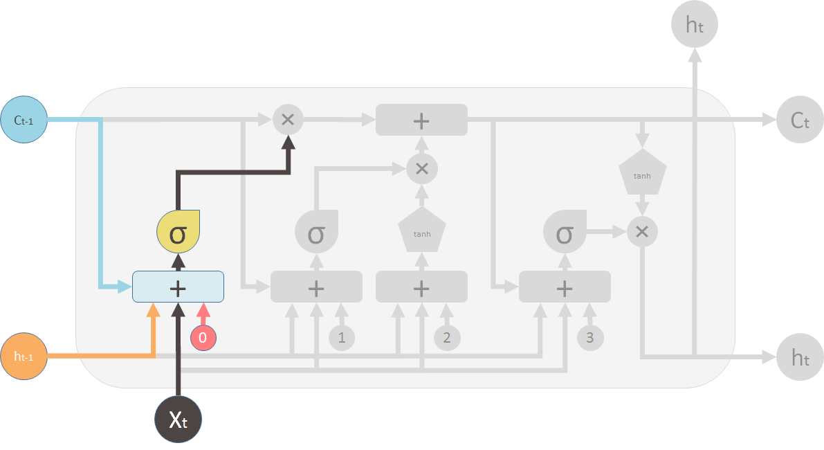
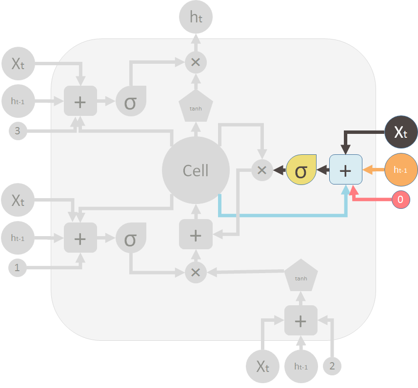
This is the forget gate (valve) that shuts the old memory:
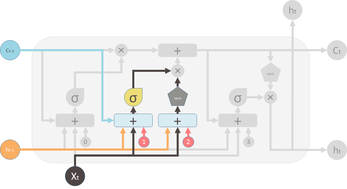
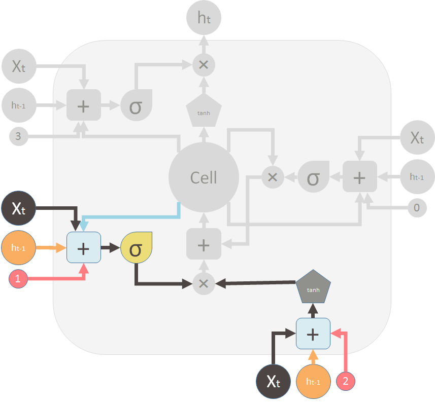
This is the new memory valve and the new memory:
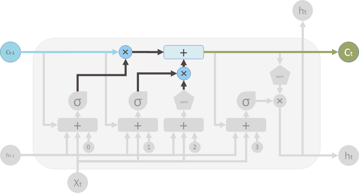
These are the two valves and the element-wise summation to merge the old memory and the new memory to form C_t (in green, flows back to the big ?Cell?):
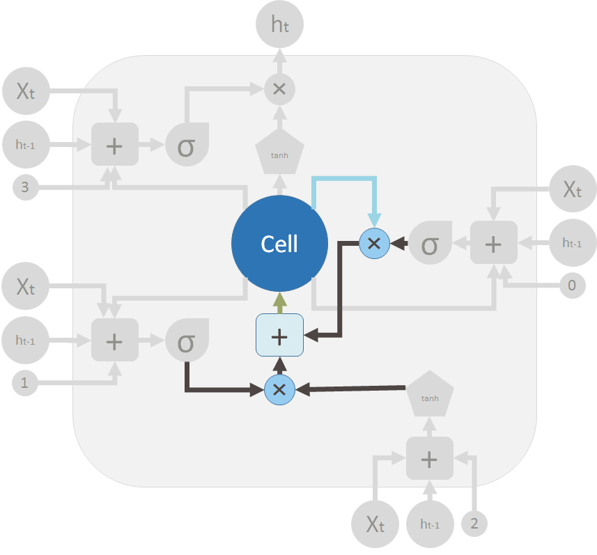
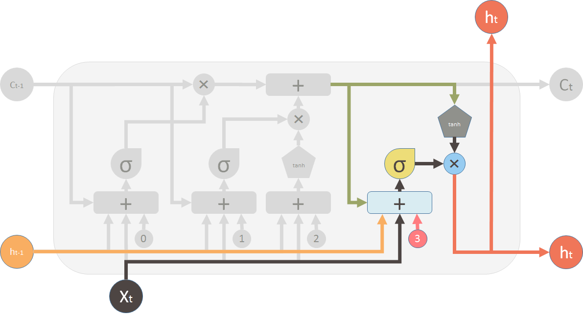
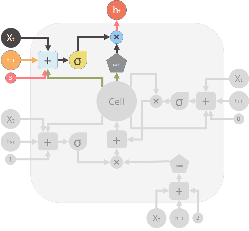
This is the output valve and output of the LSTM unit:

