The Open System Interconnection model (OSI) is a seven layer model used to visualize computer networks. The OSI model is often viewed as complicated and many fear having to learn the model. However, the OSI model is an extremely useful tool for development and problem solving. Each of the seven layers goes up in increments of one as it gets closer to the human user. Layer one ? the application layer, is closest to the person while layer seven ? the physical layer is where the network receives and transmits raw data. The OSI model belongs to the International Organization for Standards (ISO) and is maintained by the identification ISO/IEC 7498?1. In this post, each of the seven layers of the OSI model will be explained in simple terms. The layers will be explained from layer seven to layer one, as this is where the data flow starts.
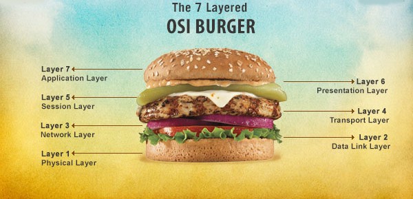
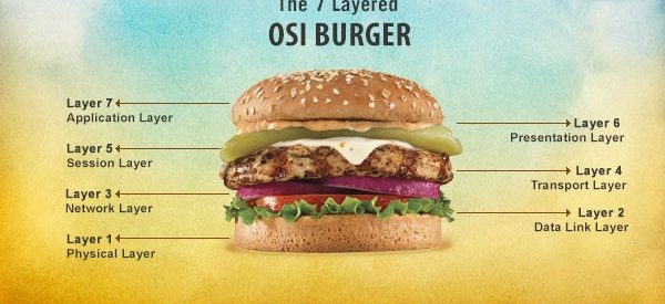
The seven layers of the OSI model
Layer 7 ? Application
The application layer is where the user inputs data and data is output to the user. The application layer is usually software that is run off the local machine, however this depends on the network architecture. The software could be cloud based, meaning it runs off a server in a remote location and data is transferred over the internet, or the software could be run on a local server. The application layer provides services for email, Telnet and file Transfer for example. An example of the application layer is an internet browser, an FTP client or even Microsoft Word.
Layer 6 ? Presentation
The presentation layer is where the operating system lies. This operating system could be Windows, OS X, a Unix based operating system or one of the many others available. Where the human user interacts with the application layer described above, the application layer interacts with the presentation layer. This may be done directly, or through a runtime environment such as the Java Runtime Environment (JRE).
Layer 5 ? Session
The session layer is responsible for creating and maintaining sessions between the operating system on the presentation layer and other, third party machines. For example, when a user is browsing the internet, they are interacting with the application layer, the application layer is interacting with the presentation layer and the session layer allows the operating system to interact with the web server.
Layer 4 ? Transport
The transport layer is responsible for the logistics of the session. In the example used above, the transport layer would be responsible for determining what and how much information is transferred between the operating system and the web server.
Layer 3 ? Network
The network layer is where routers operate. A router is a hardware device that forwards packets of information between computers on a network. This is where your IP address comes from and in the example used above, the router is responsible for sending packets of information out into the internet and receiving them. These packets origin and destination is determined by the IP address of your router.
Layer 2 ? Data link
The data link layer is where switches operate and provides a reliable link between two directly connected nodes. The data link layer is also responsible for detecting and possibly fixing any packet errors that may form on the physical layer. The data link layer is divided into two separate layers, the Media Access Control (MAC) and Logical Link Control (LLC) layers. The MAC layer is responsible for controlling how devices connected to the network gain access. The LLC layer controls error checking, possible fixes and packet synchronization.
Layer 1 ? Physical
The physical layer is literally the physical hardware that makes up the network. This layer has several major functions:
- Defining physical specifications
- Defining protocols
- Defining transmission mode (half duplex & full duplex)
- Defining the network?s topology
Hardware such as the physical components of Ethernet cables and Bluetooth are just some examples of the physical layer.
Purpose of the OSI Model
Even after reading a description of each of the seven layers, you may still be confused as to how the OSI model applies to real life networking. It?s commonly misunderstood how a model can be used to solve real-life problems and in some cases, a model may not be the best approach. However, in many aspects of Information & Communications Technology(ICT), a model can be extremely useful and that is the case for the OSI model.
When first discovering a networking problem, it can be confusing as to where you should start. The OSI model helps you to start figuring out where the problem may reside and therefore, help you to solve the problem. For example, a client?s computer is not able to reach a website. The problem is isolated to one device on the network, so it can be assumed that the problem is likely to be on the application layer. However, after testing you find that the problem still exists when you try a different web browser and so the application layer is ruled out. You then assume that the problem resides on the presentation layer and start looking for faulty settings. After some digging around you find that your client has entered some DNS settings incorrectly and so you then conclude the problem is on the presentation layer.
You may already be using the OSI model for simple problem solving such as the example above without even realizing it. However, when dealing with large, corporate scale networking a purposeful use of the OSI model can make your job much easier and more enjoyable.

