The term ?isometric? is one of the most misapplied words in the design industry. We tend to call every non-perspective 3-dimensional drawing ?isometric.?
One of the recent examples of pseudo-isometric artworks is the old Medium logo, used from 2015 to 2017 . It was designed on a parallel (axonometric) grid, but it?s not isometric at all.
 The old Medium logo was designed on a trimetric grid.
In this article I am going to explain the differences between isometric and other types of projections.
Pictorial drawings
Being able to visualize three-dimensional shapes is a skill every designer and engineer should master. This is especially important in 3D modelling. However, there is a distinct difference between drawing a view that looks like three-dimensional and creating a true 3D-model.
Real 3D-models can be rotated on the screen to be view from any angle. The computer calculates the points, angles and surfaces of the object in space. Then it displays the result on a flat screen as so-called pictorial drawings.
The word pictorial means ?like a picture.? It refers to any realistic type of drawing portraying height, width and depth of an object. Pictorial drawings are extremely useful when we need to communicate designs to people who don?t have a technical training in interpreting multiview projections.
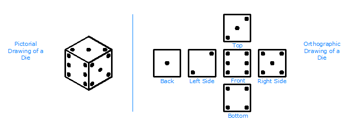 Pictorial with multiview drawings. Image source sites.google.com/site/multiviewdrawings/home.
Several forms of pictorial projections are used in design and technical drawings:
- Perspective ? most realistic drawings. Our eyes see objects in perspective. There are three types of perspective projections: one-, two- and three-point perspective.
 Three types of perspective. Image from Hamiltonian of design (hamiltonianofdesign.wordpress.com).
- Oblique ? least realistic. Only one or two faces in oblique projections have true shape and size. There are three types of oblique projections: cabinet, cavalier and general.
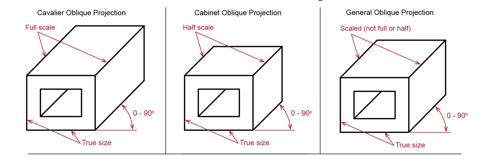 Three types of oblique projections.
- Axonometric projections are more realistic than oblique. Horizontal edges of an object in axonometric projections are parallel to each other and inclined to the plane. There are three types of axonometric projections: isometric, dimetric and trimetric.
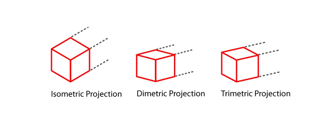 Three types of axonometric projections. Image from Hamiltonian of design (hamiltonianofdesign.wordpress.com).
Axonometric projections
Axonometric projections are the most common way of depicting 3-dimensional objects without involving perspective. Unlike perspective drawings, all axes in axonometric projections do not converge and always stay parallel.
 Perspective vs isometric. Image source: vitorials.net
No vanishing points, no horizon line. The object doesn?t get smaller with distance. It was very important for the game industry between 1980 and 1990, because computers of that era with limited resources should render an object only once.
The main purpose of axonometric projections is to show the shape and the size of an object. They were designed in the way, that you can take measurements of an objects right from these projections.
All three types of axonometric projections are built on the grid where the X and Z axes are inclined to the horizontal plane. The Y axis always stays perpendicular to the horizontal plane.
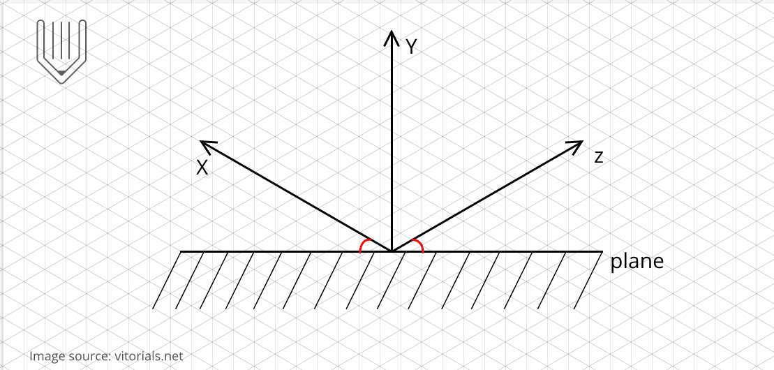 X and Z axes are inclined to the horizontal plane. Image source: vitorials.net.
The angle between the ?horizontal? X and Z axes and the horizontal plane determines the type of axonometric projection.
Isometric projection
Isometric (meaning ?equal measure?) is a type of parallel (axonometric) projection, where the X and Z axes are inclined to the horizontal plane at the angle of 30?. The angle between axonometric axes equals 120?.
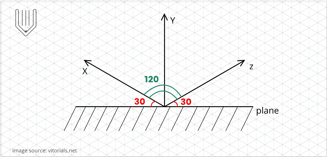 30/120/30 is also referred ti as true isometric grid.
A perfect cube in an isometric projection would look like a perfect hexagon.
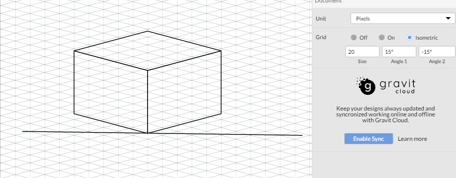
In Gravit Designer, you are able to build the true isometric grid right out of the box.
 You can adjust the size of the default isometric grid in Gravit Designer.
Because all edges of an isometric object are inclined at the same angle, they are equally foreshortened. That allows you to take measurements of each side of an object using the same scale.
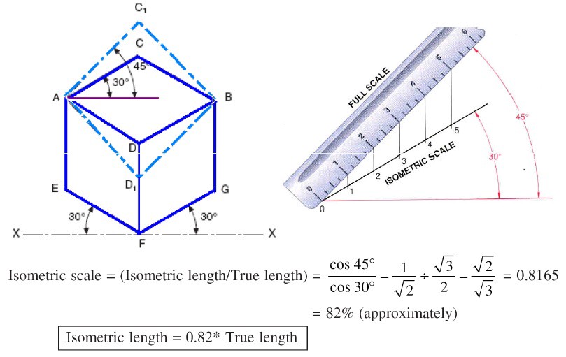 Isometric length and true length. Image source: ed-zon.blogspot.com/2013/05/isometric-projection-and-isometric.html.
Most designers ignore foreshortening during the sketching phase and build isometric views of an object with the actual length. The end result would be an isometric sketch, not a projection
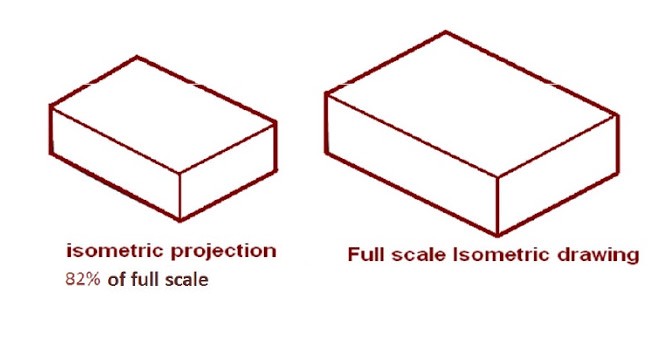 An isometric sketch is sometimes referred to as an isometric view or isometric drawing. Image source: ed-zon.blogspot.com/2013/05/isometric-projection-and-isometric.html.
How to build isometrics without a grid
Using an isometric grid is not the only way how you can draw isometric artworks in Gravit Designer.
They can be constructed right from multiview projections (top, front, side etc.). The most common and simple techniques are SR45? and SSR30?.
These are very handy methods, when you need to create anisometric mock-up of your design with a few clicks:
 Creating Isometric asset using SSR method in Gravit Designer.
SR45? technique
?SR45?? stands for scale and rotate at 45? angle. The scale ratio is 0.577 or more preciously tan(30?).
You can build isometric projections via SR45? using Gravit Designer?s transform panel in two simple steps
Step 1: rotate object at 45?
Step 2 : scale object
SSR30? technique
?SSR30?? is a more popular and flexible method of creating isometric artworks. With SSR30? you can quickly create top, left and right isometric views.
SSR30? stands for scale, skew and rotate at 30?.
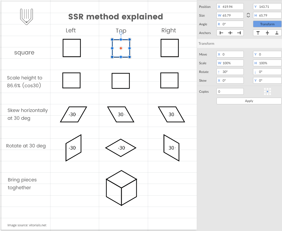 Using the SSR method in Gravit Designer. Image source: vitorials.net.
Designing other axonometric projections with Gravit Designer
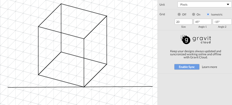
In dimetric projections only two sides are equally foreshortened. The X and Z axes are still at the same angle to the horizontal plane, but not at 30. Angles between axes are not equal.
 Common 15? dimetric grid in Gravit Designer.
Trimetric projections
All angles of an trimetric projections are different, therefore all sides (edges) and axes are foreshortened unequally.
 You can setup a trimetric grid in Gravit Designer in few seconds.
You can use a wide array of angles to build trimetric and dimetric artworks, but be sure avoid small ones. In my opinion, it makes the projection a tad too flat:
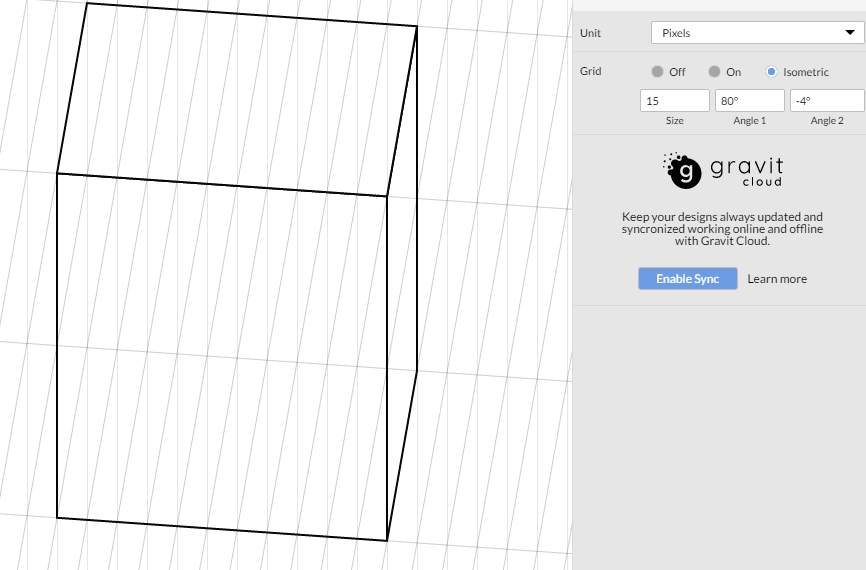 Small angles make your artwork too flat.
Anatomy of a Medium logo
The original Medium logo was designed on a non-isometric grid, where the X and Y axes are inclined to the horizontal plane at the angle of -27? and 60?, respectively. So, the Medium logo was built on trimetric grid.
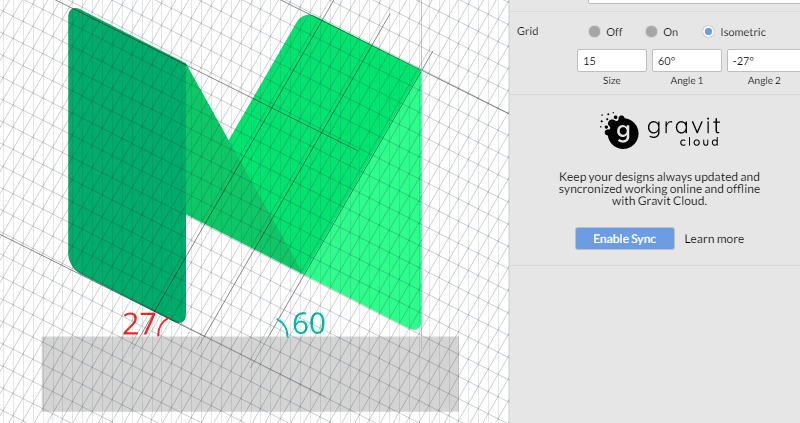 Medium previous logo was trimetric
If you made it this far, congratulations! I hope all the GIFs and JPGs didn?t give your browser (or even you ?) an overkill. I also hope you got some value for yourself and some new tools to leverage in your isometric drawings.
Website | Facebook | Twitter | Forum

