
Image Processing
In this article, we will go through simple concepts of Bitmap image format and understand how we can assemble simple BMP images from binary data in memory
 (source: pexels.com)
I was working on a Medium article to discuss Typed Arrays in JavaScript and how to create and manipulate in-memory Data Structures. Basic Text Encoding is a sweet example to handle binary data but I wanted a little complex demonstration of creating well-known file formats.
Since Bitmap or BMP is a lossless and uncompressed image format and it felt natural to encode a BMP image for demonstration. Unlike plain text encoding, BMP is complicated because of the so-called required metadata.
My first thought was to; understand how BMP encoding works, so I went on the ?internet?. It took painstaking hours to discover something useful. By doing trial-and-error, I finally arrived at some conclusions.
In this article, we will discuss what BMP image is consists of, what are the encoding parameters of the BMP image format and how we can create some simple BMP images just by playing with binary values.
Disclaimer: The concepts discussed in this tutorial are not meant to be applied in production, especially when dealing with efficiency and performance. There are other great image formats like PNG, JPEG and WebP for storing and transferring image data over a network. Also, I am not a professional when comes to image processing, so please correct me if I made a mistake anywhere.
About Bitmap images
A bitmap image is a raster image (containing pixel data as opposed to vector images) format. Each pixel of a bitmap image is defined by a single bit or a group of bits. Hence, it is called the bitmap or a map of bits and pixels.
Bitmap AKA Device Independent Bitmap (DIB) was designed by Microsoft Corporation to easily exchange images between different devices without worrying about the device?s logic to display raster images on the screen. These files have .bmp or .dib extensions.
Technically, a Bitmap image is an uncompressed file format which means, every pixel of an image has its own bit (or group of bits) in the file. However, some other formats like PNG and JPEG, they use some compression methods to group similar pixels to decrease overall file size.
Hence, technically PNG or JPEG image is a map of bits but they are not called bitmaps because they are compressed. The Lossy Compression is a compression algorithm that changes pixel information to decrease filesize without too much harming the image details. Since BMP is not compressed, it is lossless. Hence BMP images are much larger in size.
However, BMP images can optionally be compressed using lossless algorithms like Huffman and RLE compression.
BMP allows encoding images in different color depths. The color depth is a measure of an individual image pixel to accurately represent a color. Color depth is calculated in bits-per-pixel or bpp.
For example, 1-bit color depth or 1bpp means a pixel can have a 1-bit color or 2 values. Monochromatic images have 1-bit color depth because a pixel can be true black or true white. BMP format supports 1-bit, 2-bit, 4-bit, 16-bit, 24-bit, and 32-bit color depths. BMP allows an alpha-channel to add transparency in the image using 32-bit color depth.
Since Bitmap images are great at storing raw-uncompressed data, they are great for archival purpose and image processing.
BMP file format
From here onwards, we will use BMP term to specify a Bitmap image format without any compression of any kind.
Every file in your computer is made of binary numbers, whether that is an image file or a text file. These binary numbers represent the content of the file and a computer decodes that information in the CPU (eventually).
A plain-text file contains only text (without any styling or file metadata). Each character of the text is represented by their code-point (a decimal number assigned to each character). So if view a plain-text file in a binary, all binary numbers represent characters only.
I have explained plain-text file, character encoding, code point and binary representation in great detail in this article.
In contrast, an image file contains information other than pixels. For example, the width and height of an image (in pixels), size of the image (in bytes), bit-depth of pixels (in bpp), color pallets, etc. This is called metadata.
A BMP file format contains different sections that contain information about metadata, color pallet, and actual pixel data.
 (BMP File Structure)
In this image, we can see 4-blocks dedicated to representing each distinct information about the image. When an image parser (like an image viewer application or a browser) reads the BMP image, it will read all these blocks and construct an image to display on the screen.
Let?s understand the role of each of these blocks.
Block 1: File Type Data
This block is a BMP Header labeled as BITMAPFILEHEADER (the name comes from c++ struct in Windows OS). This is the starting point of the BMP file and has 14 bytes width. This header contains a total of 5 fields of variable byte width. These are mentioned in the below table.
(BITMAPFILEHEADER Fields)
One thing to remember is that BMP uses the little-endian system to store a number (integer or float) when a number is larger than 1-byte.
For example, 312 decimal value in 2-bytes binary is 00000001 00111000 and its hex byte representation is 0x01 0x38. Similarly, in 4-bytes, it is 00000000 00000000 00000001 00111000 or 0x00 0x00 0x01 0x38.
But in the little-endian system (in modern computers), the least-significant byte (LSB) is stored first. Therefore, 312 decimal value in hex byte representation will be 0x38 0x01 0x00 0x00 and BMP will construct binary value like RHS: 0x38 <- 0x01 <- 0x00 <- 0x00 :LHS.
I have explained little endian and big-endian system in great detail in this article and it?s something worth checking out.
Block 2: Image Information Data
This is a DIB Header must be used to specify the color and image information. Unlike BITMAPFILEHEADER, there are many types of info headers (listed on the Wiki page). Each header has different byte-width but for compatibility reasons, we use BITMAPINFOHEADER.
This header is 40-bytes wide and contains a total of 11 fields of variable byte widths. These are mentioned in the below table.
(BITMAPINFOHEADER Fields)
Block 3: Color Pallet (semi-optional)
This block contains the list of colors to be used by a pixel. This is an indexed table with the index starting from 0. The integer value of the pixel points to the color index in this table and that color is printed on the screen.
However, this block is mandatory when BitsPerPixel is less than or equal to 8, hence this block is semi-optional. When the BitsPerPixel is 16, 24 or 32, the color value of a pixel is calculated from the combination of individual Blue, Green and Red values defined by the pixel.
Hence, 1, 4 and 8-bit color depth BMP images are called palletized images and each individual pixel of the image is called palletized pixel.
The below table contains information about the maximum possible colors for a given BitsPerPixel(bpp) or bit-depth.
If our bpp ? 8, then we need to define a color pallet. TotalColors in BITMAPINFOHEADER header is the number are colors we have defined in the color-pallet. However, we can set TotalColors to 0 which means we want to utilize maximum colors (2^BitsPerPixel).
When bpp > 8, we should ignore adding color-pallet to the BMP image and set TotalColors to 0. In this case, the color of a pixel will be derived from RGB channels (and alpha-channel in the case of 32bpp). We will talk about how RGB values are interpreted when we will create BMP images.
The ImportantColors value in BITMAPINFOHEADER header is used when bpp ? 8. But in all the cases, it should be set to 0. This answer on the Adobe Forum explains the ImportantColors field in greate detail.
Quote: This is the number of colors that are considered important when rendering the image. For instance, an image might contain 47 different colors but perhaps a reasonable image can be generated using just 13 of them. If the image is displayed on hardware having the very limited color capability, say a cheap LCD panel supporting only 16 colors, then the reader knows that it should be able to generate an acceptable image by just using the first 16 colors in the Color Table. Needless to say, the important colors need to be stored first in the Color Table for this to work. It is left up to the application reading the file to determine how to map the ?unimportant? colors into the available ones. If this parameter is equal to zero, then all colors in the Color Table are to be considered important.
Each entry in this table is 4-bytes wide. 3-bytes are allocated to define the intensity of the Red, Green and Blue color-channels respectively. Each byte defines 256 unique values of each color channel. 4th byte is reserved and should be set to 0.
Hence, the size of this block variable and depends on the number of color entries in this block. In nutshell, the total size of this block is 4 x N bytes where N is the total entries in the color pallet.
Block 4: Raw Pixel Data
This block contains binary numbers dedicated to representing the unique color values of each individual pixel. Depending on the bpp of the BMP image, a byte can contain color values of multiple pixels or multiple bytes can be used to represent the color value of a single pixel.
The size of this block, however, is not that straightforward to calculate. BMP scan lines need padding bytes (which will learn in the next section) and hence, we will be able to calculate size once we have written all the bytes.
Total BMP File Size
The FileSize field in BITMAPFILEHEADER header is the sum of all the bytes in these 4 blocks. We could set the value of this field to 0 and it might work in all the BMP rendering applications but doing that should be avoided.
 (BMP File Structure)
BMP Scanning
Scanning is a process of resolving pixel colors by scanning the Pixel Data. Since we have provided sufficient metadata in BITMAPFILEHEADER and BITMAPINFOHEADER headers, a BMP renderer knows how to render the BMP.
To construct an image, we need to know how many bits or byte an individual pixel contains in the Pixel Data. For the sake of convenience, let?s say, each pixel can be printed using just 1 byte. Hence our pixel data will have N x M bytes to construct an image of size N x M pixels.
The coordinates of a BMP image start from the bottom-left corner much like a normal graph or northeast quarter of the 2D cartesian coordinate. Hence, BMP follows the bottom-up approach for scanning.
The first pixel of the last row in the BMP image is represented by the first byte in the Pixel Data. Then the scan moves forward by mapping the next pixel with the next byte in the Pixel Data until the last pixel in that row.
A scan line is analogous to the row of pixels. Since BMP follows bottom-up scanning, the first scan line is the last row of the BMP image. Once a scan line constructed pixel for that row, then it moves up by one row and starts resolving pixels from the Pixel Data for that row.
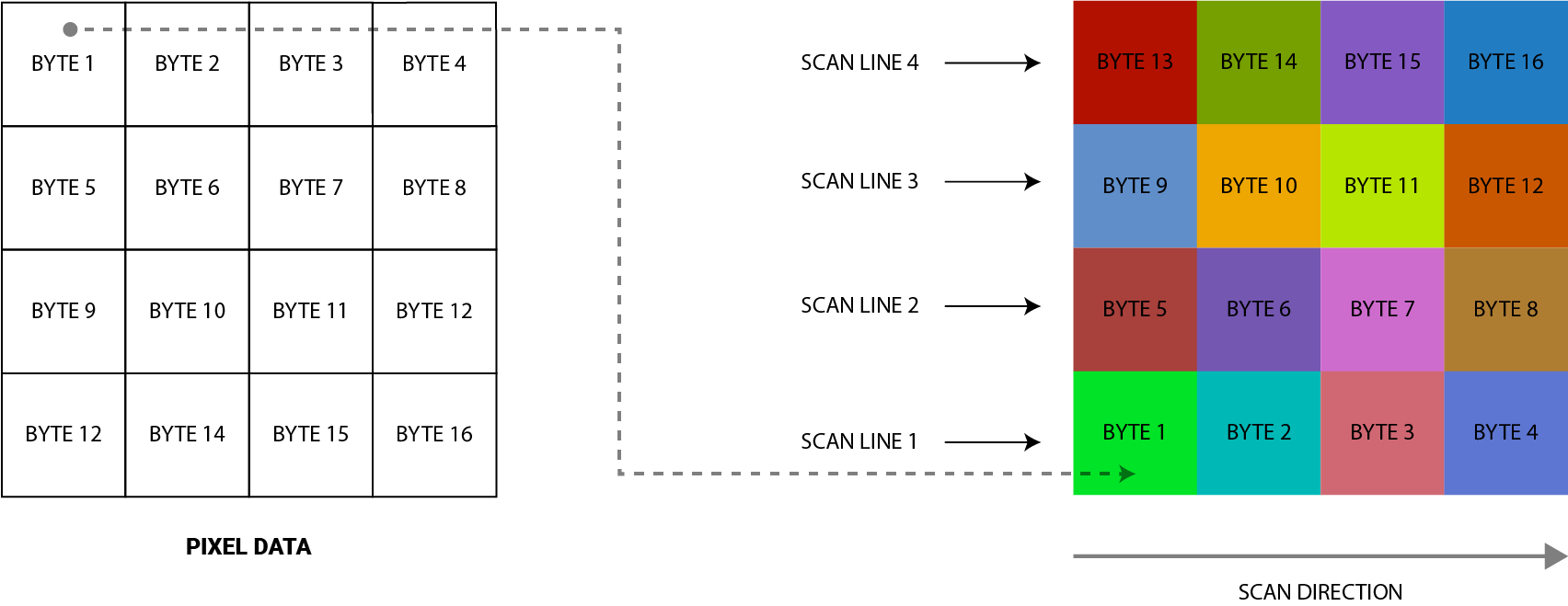 (BMP Scanning Process)
In the above example, we are creating a 4 x 4 pixels BMP image and for the sake of convenience, we can say 1px can be successfully printed by just 1-byte. For the sake of understanding, we have broken down Pixel Data into a 4 x 4 grid but in reality, it will be just a continuous stream of bytes.
I am sure from the above example, you have understood how the scan is undergoing and how each pixel is mapped with each byte in the Pixel Data.
The padding of the scan line
In the real world, a pixel can take few bits to few bytes to define its color. This purely depends on BitsPerPixel value. But in any case, every pixel of a BMP is defined by an equal size.
However, for consistency and simplicity, each scan line is 0-padded to the nearest 4-byte boundary. This means, when BMP is scanning a row of the image, it considers a block of pixels that is divisible by 4 bytes.
If an image is 4 pixels wide which also means the image row is made of 4 pixels and bpp is 8 which means 1 pixel can be defined by 1 byte. In that case, the image will consider blocks of 4 bytes in Pixel Data. If the same image is 3 pixels wide, we need to add 1 extra byte as padding.
Constructing 24-bit Bitmap Image
Let?s start with a 24 bits-per-pixel Bitmap image since it is easy to understand. From our earlier discussion, we know that the 24 bit BMP does not have the Color Pallet block.
Each individual pixel color is constructed using Red, Green and Blue color channels. Each color takes 8 bits or 1-byte of the color value. The1st byte is for Blue, 2nd for the Green and 3rd for the Red color channel.
For simplicity, let?s construct an image of 5 X 5 resolution. The first thing we need to do is to calculate field values for BITMAPFILEHEADER and BITMAPINFOHEADER headers.
(Bitmap header values for 24bit 5×5 BMP image)
From the above table, you can notice that all values are written in little-endian order (least-significant byte first). The FileType value is set to 0x42 0x4D to represent BM. This value is also called as Magic Bytes.
PixelDataOffset value is 54 because the combined total value of the Bitmap headers is 54 bytes. Since the Pixel Data in the image starts right after that (as no Color Pallet block), 54 is the offset value of the Bitmap image and 0x36 is its value in hexadecimal.
Since we are using BITMAPINFOHEADER, the HeaderSize is 40 bytes or 0x28 in hexadecimal. Since our image is 5px by 5px, ImageWidth and ImageHeight is 0x05 in hexadecimal. Also, as bpp is 24, we have set BitsPerPixel to 0x18. Also, Planes are set to 0x01 to represent 1 color plane.
Other field values are set to their default values as recommended. I have deliberately set FileSize to 0 for simplicity. But in the real world, you should set it to the number of bytes contained in that image.
I am using the Hex Field editor to manipulate the binary content of a file. You can choose any Hex Editor of your choice. First, we will create an empty image BMP file with .bmp extension (you can use touch command).
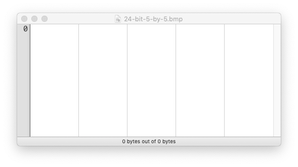 (Hex Fiend Preview)
If you open this file in a hex editor, it will show nothing because our image file is empty. And if you try to open this file in an image viewer application, it won’t work either because this file does not have any content.
I would recommend you to use a plain text editor to work with binary data. You can structure header field values separated by spaces and newlines. Once you have written all the data in hexadecimal, you can paste it in the hex editor. Hex editor can remove unnecessary spacing and newlines.
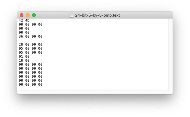 (Bitmap Header Values)
Let?s first write hex values for all header fields. From the above screenshot, we have written all the header field values in hexadecimal but without 0x prefix. This is the entire metadata of the BMP file we are about to create.
The next part is writing Pixel Data. Since the bit-depth of our image is 24, we have 3 bytes to represent a BGR color in the order. Since we have 5 pixels per row, we have 15 bytes in a row. We need to add 1 extra byte at the end of a row for padding such that total row bytes become divisible by 4 bytes.
For simplicity, let?s have all pixels of the image black. That means the total value of a pixel will be 0 or 0x00 0x00 0x00 in hex representation. We need 5 rows like this to make up the entire image (5 pixels height).
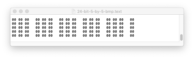 (Bitmap PIXEL DATA values)
Now that we have the entire BMP file data, it?s time to copy the context of the text file in a hex editor. Once you press save in the hex editor, this binary data will be written to the .bmp file. Now, you will be able to see the image, though you might need to zoom in as our image is only 5 X 5 pixels wide.
When you paste the text content in a hex editor, it will trim extra whitespaces and newlines. Though, it depends on what kind of hex editor you are using.
(Bitmap Data: https://gist.github.com/thatisuday/e52445255c7d60be2bc2d034c6d26c07)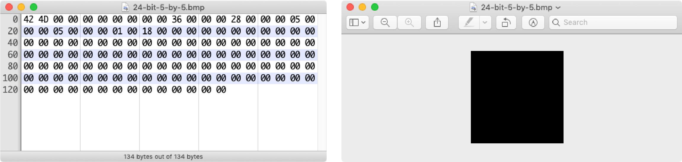 (134 bytes 24-bit BMP image in the hex editor and its image preview)
Hurray! We did it. We have created a BMP image without using any software or an application. We also found that the total byte count of the image is 134, which is our final image size. We can use this number to replace FileSize field value which would be 0x86 in hexadecimal.
But our image does not look pretty and we can?t also identify unique pixels. Let?s modify pixel values. Since with 24bit color depth, we have more than 16M colors to play with.
We can change the values of Red, Green, and Blue color channels to create different colors. The final color value depends on the combination of individual color intensities of Red, Green, and Blue and the intensity of a color is defined by its bytes value.
I have created this web tool to generate color values for Bitmap images. You can generate color values in decimal, hexadecimal, and binary formats.
For simplicity, I have changed the color values of the corner pixels and the center pixel of the image and their values look like below.
FF FF FF 00 00 00 00 00 00 00 00 00 00 FF FF 0000 00 00 00 00 00 00 00 00 00 00 00 00 00 00 0000 00 00 00 00 00 00 FF 00 00 00 00 00 00 00 0000 00 00 00 00 00 00 00 00 00 00 00 00 00 00 0000 00 FF 00 00 00 00 00 00 00 00 00 FF 00 00 00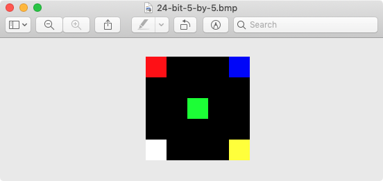 (Bitmap Image)
From the Pixel Data and BMP image preview, you can see that Bitmap scans the image bottom-up. The first 3-bytes block in the Pixel Data is FF FF FF which generates the white color. Since BMP scans the image bottom-up (from left to right in a row or scan line), the bottom-left pixel will be white.
Similarly, the last 3-bytes block in the Pixel Data is blue and it will be used to paint the top-right pixel of the image since it is the last scan point.
Constructing 16-bit Bitmap Image
A 16-bit Bitmap image is similar to a 24-bit Bitmap image in almost all aspects. However, now we have only 2-bits to define a color value.
The only change we need in file metadata is BitsPerPixel value which is 16 or 0x10 in hexadecimal. Rest all field values should be the same.
Similar to 24-bit Bitmap, the color of a pixel is calculated by combined intensities of RGB color channels. Each color channel takes 5-bits of the pixel value while the leftover most significant bit (MSB) is 0. The decimal number generated by a 15-bit binary number is used to draw the pixel color.
Since we have 15 bits to play with, the first 5 bits represent the intensity of the Red color, next 5 bits represent the intensity of the Blue color and the last 5 bits represent the intensity of the Green color.
[ 0 XXXXX XXXXX XXXXX ] —– —– —– R G B
Therefore, the color values of colored pixels used in the 24-bit Bitmap image is represented below (in 16-bit Bitmap image).
RED 0111110000000000 => 01111100 00000000 => 0x7C 0x00GREEN 0000001111100000 => 00000011 11100000 => 0x03 0xE0BLUE 0000000000011111 => 00000000 00011111 => 0x00 0x1FWHITE 0111111111111111 => 01111111 11111111 => 0x7F 0xFFYELLOW 0111111111100000 => 01111111 11100000 => 0x7F 0xE0
However, since Bitmap format uses the little-endian format to store a decimal number, we have to swap hexadecimal representation of the color value in the above table, such that the first byte is the least-significant-byte (LSB).
Since pixel color values are represented by 2 bytes and we have 5 pixels in a row, that would be a total of 10 bytes per row. But since a row must have bytes divisible by 4 bytes, we need to add 2 padding bytes per row.
(Bitmap Data: https://gist.github.com/thatisuday/2beda91b5220571fc6c499649dc551be)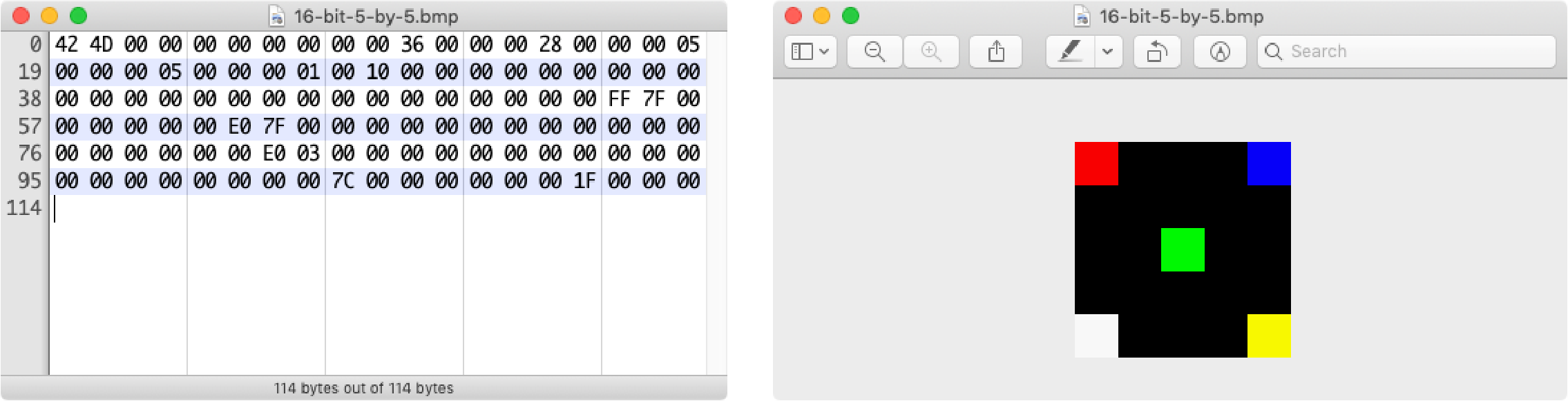 (114 bytes 16-bit BMP image in the hex editor and its image preview)
Using 16bpp, we were able to create the same image but with lower size (reduced by 20ytes). However, the difference is not that suttle because we are using color channels at their maximum intensity.
A 16-bit Bitmap image offers around 65K colors to play with, however, a 24-bit bitmap offers 16.7M colors to play with. Hence we need an image with maximum colors for the better viewing experience, we should go for 24bpp.
Constructing Monochromatic Bitmap Image
The monochromatic image is an image composed of only two colors. People generally get confused between B/W vs monochromatic images. All black and white images are monochromatic but not all monochromatic images are black and white. It?s just a matter of a choice between two colors.
Since a pixel can take 2 color or 2 color values, the BitsPerPixel of a monochromatic image is 1. And we have learned that if bpp ? 8, then we have defined a color pallet in the Color Pallet block.
In the monochromatic color pallet, we have only 2 entries. The first entry of the color pallet has index 0 while 2nd entry has index 1. Since a single bit is used to define a pixel color, when bit is 0, the first color from the pallet is used and when the bit is 1, the second color is chosen.
Each entry of the color pallet takes 4 bytes to define a color. The first byte represent the intensity of the Red color channel, the second by for the Blue channel and the third byte for the Green channel. The last byte is reserved for other purposed and should be set to 0x00.
Since the color pallet contains 2 entries and each entry takes 4 bytes, the size of the Color Pallet block is 8 bytes. Hence, we should set BitsPerPixel value to 1 in decimal and PixelDataOffset to 62 in decimal.
For simplicity, let?s have the pure white color as the first entry and pure black color as the second entry of the color pallet. With this configuration, the Color Pallet block will look like below.
FF FF FF 0000 00 00 00
Since the value of each individual pixel points to the index in the color pallet, we don?t have to worry about setting the intensity of the pixel color in the Pixel Data block. Each pixel is identified by 1 bit in the Pixel Data.
In our case, a row of 5 pixels takes only 5 bits. That means, 1 byte is more than sufficient to draw a row of our image. The last 3 bits of that byte should be 0. Also, we need 3 more bytes for the padding in each row.
So in nutshell, we are drawing 5 X 5 black and white pixel images. Since we are working with a very simple configuration, let?s draw the cross.
00100 000 00000000 00000000 0000000000100 000 00000000 00000000 0000000011100 000 00000000 00000000 0000000011111 000 00000000 00000000 0000000000100 000 00000000 00000000 00000000
In the above Pixel Data block, you can clearly see the cross. However, the cross is upside down because Bitmap scans the image bottom-up. The pixels with value 0 will be white because they point to the index:0 color in the color pallet and pixels with value 1 to the index:1 color which is black.
(Bitmap Data: https://gist.github.com/thatisuday/caf0dd9188386c53551639084c9be3a3)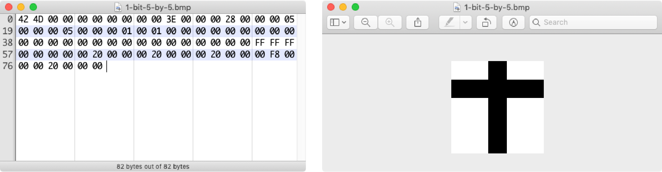 (82 bytes monochromatic BMP image in the hex editor and its image preview)
You are free to choose any two colors in a monochromatic Bitmap image. Since the color in the Color Pallet is defined by 3 bytes RGB value, we have 16.7M colors to play with.
If you have noticed, we haven?t set the TotalColors value and it is still 0 in decimal. We did this because we are adding 2^BitsPerPixel (which is 2^1 or 2 in decimal) entries in the color pallet.
4-bit and 8-bit Bitmap images
Similar to the monochromatic image, 4-bit and 8-bit Bitmap images need a color pallet. However, a 4-bit color pallet can have at max 16 entries and an 8-bit color pallet can have 256 entries.
The way a pixel can point to an index of the color entry in the color pallet is the same as the monochromatic image. However, in the case of a 4-bit image, a pixel value is defined with 4 bits and for the 8-bit image, a pixel value is defined with 8 bits. This means, 1 byte of Pixel Data represents 2 pixels.
Does that mean for an 8-bit Bitmap image, we have to define 256 entries in the color pallet? That sounds boresome. The answer is no. We don?t have to define all the entries, just that we save a maximum of 256 entries.
If we are adding fewer entries than maximum, then it?s our responsibility to set TotalColors field value which should be equal to the number of actual entries in the color pallet. We also need to adjust PixelDataOffset the value accordingly by considering the size of the Color Pallet block.
If a pixel value resolves to an entry index that does not exist in the color pallet, then the pixel will acquire a black color.
About 32-bit Bitmap Image
Adding transparency to Bitmap images is not as easy as it sounds. Transparent Bitmaps are not supported by all the applications.
Normally, a 32-bit Bitmap image is the same as a 24-bit Bitmap image. In both formats, 3 bytes are used to represent the values of RGB color channels. In the case of 32-bit Bitmaps, the 4th byte is used to represent a transparency value.
However, BITMAPINFOHEADER ignores the 4th byte for 32-bit Bitmap images. You should read this Wiki article on 32bpp Bitmap images and how transparency can be achieved using the BITFIELDS mechanism.
Since transparency is not widely supported for BMP formats, you can always go for PNG or WebP formats.
 (thatisuday.com / GitHub / Twitter/ StackOverflow / Instagram)
![]()

