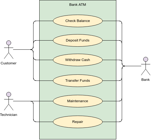
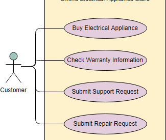
A use case describes how a user uses a system to accomplish a particular goal. A use case diagram consists of the system, the related use cases and actors and relates these to each other to visualize: what is being described? (system), who is using the system? (actors) and what do the actors want to achieve? (use cases), thus, use cases help ensure that the correct system is developed by capturing the requirements from the user?s point of view.
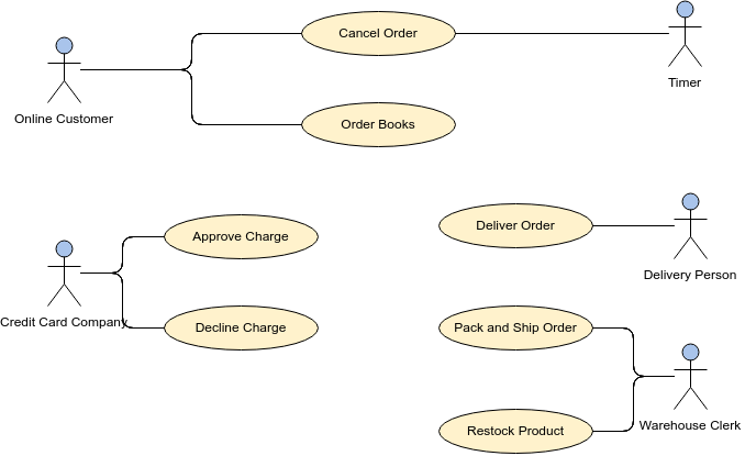
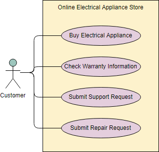 Online Store Use Case Diagram
Origin of Use Case
These days use case modeling is often associated with UML, although it has been introduced before UML existed. Its brief history is as follow:
- In 1986, Ivar Jacobson first formulated textual and visual modeling techniques for specifying use cases.
- In 1992 his co-authored book Object-Oriented Software Engineering ? A Use Case Driven Approach helped to popularize the technique for capturing functional requirements, especially in software development.
Purpose of Use Case Diagram
Use case diagrams are typically develop in early stage of development and people often apply use case modeling for the following purposes:
- Specify the context of a system
- Capture the requirements of a system
- Validate a systems architecture
- Drive implementation and generate test cases
- Developed by analysts together with domain experts
What is a Use Case Diagram in UML?
A use case is a list of actions or event steps typically defining the interactions between a role of an actor and a system to achieve a goal. A use case is a useful technique for identifying, clarifying, and organizing system requirements. A use case is made up of a set of possible sequences of interactions between systems and users that defines the features to be implemented and the resolution of any errors that may be encountered.
While a use case itself might drill into a lot of detail (such as, flow of events and scenarios) about every possibility, a use-case diagram can help provide a higher-level view of the system, providing the simplified and graphical representation of what the system must actually do.
A use case (or set of use cases) has these characteristics:
- Organizes functional requirements
- Models the goals of system/actor (user) interactions
- Describes one main flow of events (main scenarios) and possibly other exceptional flows (alternatives), also called paths or user scenarios
Use Case Diagram Notations
Use cases define interactions between external actors and the system to attain particular goals. A use case diagram contains four main components
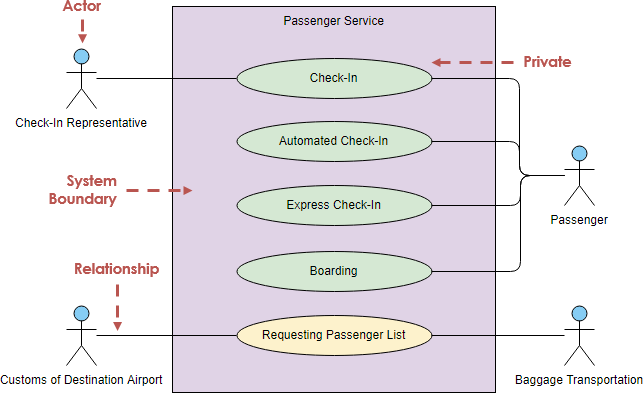
Actor
Actors are usually individuals involved with the system defined according to their roles. The actor can be a human or other external system.
Use Case
A use case describes how actors uses a system to accomplish a particular goal. Use cases are typically initiated by a user to fulfill goals describing the activities and variants involved in attaining the goal.
Relationship
The relationships between and among the actors and the use cases.
System Boundary
The system boundary defines the system of interest in relation to the world around it.
Benefits of Use Case Diagram
- Use cases is a powerful technique for the elicitation and documentation of black-box functional requirements.
- Because, use cases are easy to understand and provide an excellent way for communicating with customers and users as they are written in natural language.
- Use cases can help manage the complexity of large projects by partitioning the problem into major user features (i.e., use cases) and by specifying applications from the users? perspective.
- A use case scenario, often represented by a sequence diagram, involves the collaboration of multiple objects and classes, use cases help identify the messages (operations and the information or data required ? parameters) that glue the objects and classes together.
- Use cases provide a good basis to link between the verification of the higher-level models (i.e. interaction between actors and a set of collaborative objects), and subsequently, for the validation of the functional requirements (i.e. blueprint of white-box test).
- Use case driven approach provides an traceable links for project tracking in which the key development activities such as the use cases implemented, tested, and delivered fulfilling the goals and objectives from the user point of views.
How to Draw a Use Case Diagram?
A Use Case model can be developed by following the steps below.
- Identify the Actors (role of users) of the system.
- For each category of users, identify all roles played by the users relevant to the system.
- Identify what are the users required the system to be performed to achieve these goals.
- Create use cases for every goal.
- Structure the use cases.
- Prioritize, review, estimate and validate the users.
Note that: to make use case approach more ?Agile?, do not detail all use cases, but prioritize them in your product backlog, you should refine the use case in different level of details according to the development phase with just-in-time and just-enough manner.
You can also:
- Draw packages for logical categorization of use cases into related subsystems.
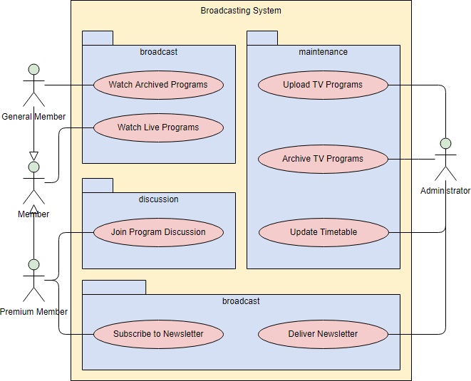
Structuring Use Cases
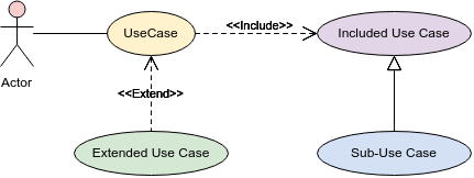
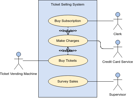
UML defines three stereotypes of association between Use Cases:
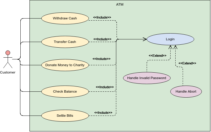
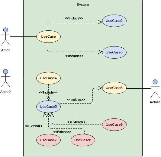
<<include>> Use Case
The time to use the <<include>> relationship is after you have completed the first cut description of all your main Use Cases. You can now look at the Use Cases and identify common sequences of user-system interaction.

<<extend>> Use Case
An extending use case is, effectively, an alternate course of the base use case. The <<extend>> use case accomplishes this by conceptually inserting additional action sequences into the base use-case sequence.
![]()
Abstract and generalized Use Case
The general use case is abstract. It can not be instantiated, as it contains incomplete information. The title of an abstract use case is shown in italics.
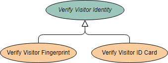
Example
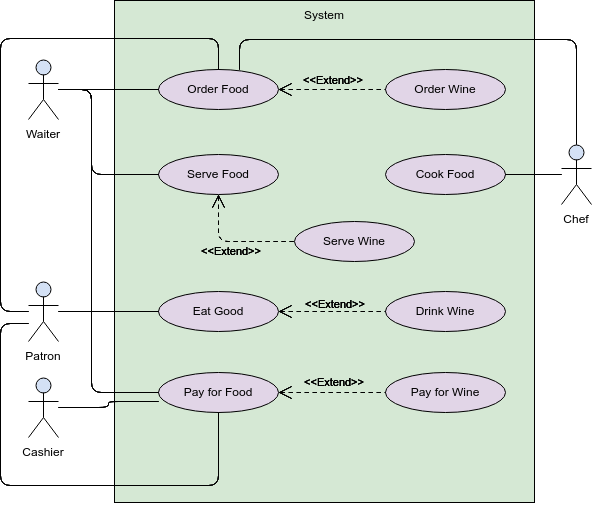
This example depicts a model of several business use cases (goals) which represents the interactions between a restaurant (the business system) and its primary actors.
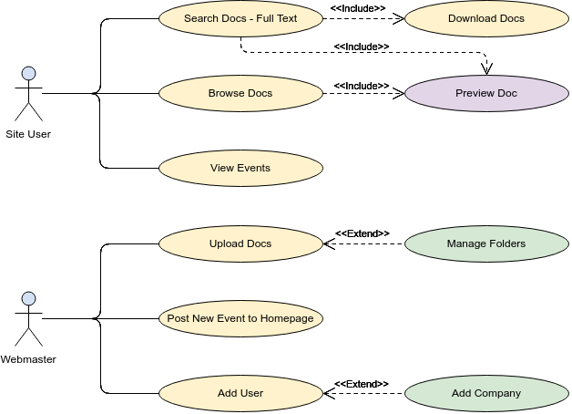
After the base use cases have been identified in the first cut, perhaps we could further structuring those use case with <<extend>> and <<include>> use cases in the second round touch up as shown in the Figure below:
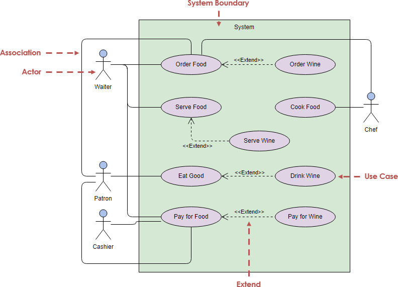
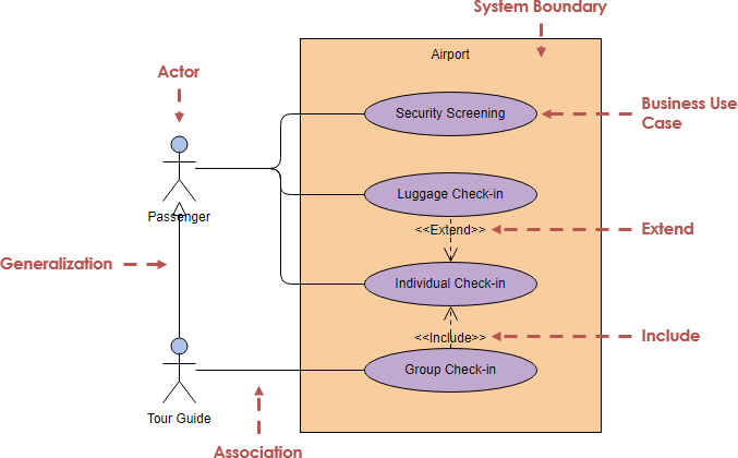
Business Use Case
A business use case is described in technology-free terminology which treats the business process as a black box and describes the business process that is used by its business actors, while an ordinary use case is normally described at the system functionality level and specifies the function or the service that the system provides for the user. In other words, business use case represents how the work to be done manually in the currently situation and it is not necessarily done by the system or intend to be automated in the scope of target system.
How to Identify Actors
Often, people find it easiest to start the requirements elicitation process by identifying the actors. The following questions can help you identify the actors of your system (Schneider and Winters ? 1998):
- Who uses the system?
- Who installs the system?
- Who starts up the system?
- Who maintains the system?
- Who shuts down the system?
- What other systems use this system?
- Who gets information from this system?
- Who provides information to the system?
- Does anything happen automatically at a present time?
How to Identify Use Cases?
Identifying the Use Cases, and then the scenario-based elicitation process carry on by asking what externally visible, observable value that each actor desires. The following questions can be asked to identify use cases, once your actors have been identified (Schneider and Winters ? 1998):
- What functions will the actor want from the system?
- Does the system store information? What actors will create, read, update or delete this information?
- Does the system need to notify an actor about chances in the internal state?
- Are there any external events the system must know about? What actor informs the system of those events?
Use Case Diagram Tips
Now, check the tips below to see how to apply usecase effectively in your software project.
- Always structure and organize the use case diagram from the perspective of actors.
- Use cases should start off simple and at the highest view possible. Only then can they be refined and detailed further.
- Use case diagrams are based upon functionality and thus should focus on the ?what? and not the ?how?.
Use Case Levels of Details
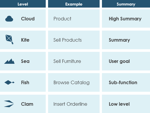
Use case granularity refers to the way in which information is organized within use case specifications, and to some extent, the level of detail at which they are written. Achieving the right level of use case granularity eases communication between stakeholders and developers and improves project planning.
Alastair Cockburn in Writing Effective Use Cases gives us an easy way to visualize different levels of goal level by thinking in terms of the sea:
Note that:
- While a use case itself might drill into a lot of detail about every possibility, a use-case diagram often be used for a higher-level view of the system as blueprints.
- It is beneficial to write use cases at a coarser level of granularity with less detail when it?s not required.
I hope you can answer ?what is use case diagram? now and can apply use case in your project. If you want to learn more about other UML diagram types, please check the UML guide: Overview of the 14 UML Diagram Types.
Just showing the use case diagram in UML notation is not enough. Each use case accompanied by text explaining the purpose of the use case as well as what functionality is accomplished when a use case is executed.
The use case specification is typically created in analysis and design phase in an iterative manner.
- At first, only a brief description of the steps needed to carry out the normal flow of the use case (i.e., what functionality is provided by the use case) is written.
- As analysis progresses, the steps are fleshed out to add more detail.
- Finally, the exceptional flows are added to the use case
- Each project can adopt a standard use case template for the creation of the use case specification.
Use Case vs Use Case Specification
A Use Case describes a task that is performed by an actor yielding a result of business value for a business. A use case may be visualized as a use case diagram or/and in structured textual specification format:
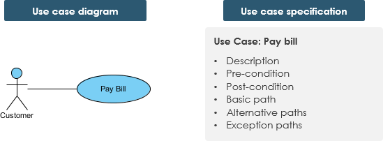
Use Case (task ? a customer want to perform) may be:
- Interactive ? A system use case describes an actor?s interaction with a system in pursuit of the defined business goal
- Manual ? A sequence of actions performed by an actor
- Automated ? A sequence of steps performed by a program or script
Characteristics of Use Cases
A use case has:
- Only one goal
- A single starting point
- A single ending point
- Multiple paths for getting from start to finish
- i.e. Specify behavior for a variety of possible conditions
- Each conditions may require specific action(s)
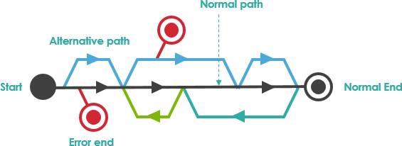
For Example ? Customer pays bill:

There are multiple paths to achieve the goal:
- Telephone payment
- By mail
- In person
- by check
- by cash, etc.
A path that does not lead to the goal:
- Credit card is declined
Agile Use Case Approach
The use case model and its individual use cases evolve level by level over time. Not all use cases of a model will necessarily need to be specified to the same level of detail.
Just-in-Time and Just-Enough
Use cases can be written at differing levels of data and scope, each serves a purpose:
- Summary: General descriptions and sweeping overviews of system functionality or business processes.
- User Level : Task-related descriptions of users and how they interact with the system; descriptions of a specific business process. User-Level use cases are usually considered to be at the level of task that is the main work of the user.
- Sub-function: Descriptions of lower-level activities that are used to complete subparts of a core use case.
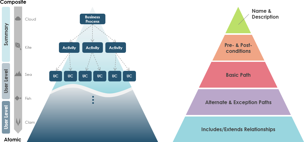
Note: Some use cases may be sufficiently specified up to level II. You stop when sufficient detail is achieved using just-in-time and just-enough manner.
A Detailed Use Case Specification
The detailed use case is a textual representation illustrating a sequence of events together with other related use case information in certain format. People typically adopt a standard use case template for recording the detailed information for the use cases
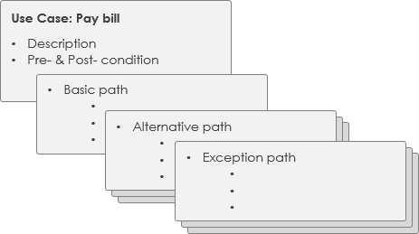
Use Case Template ? ATM withdraw case example
As mentioned before, there are several notation styles for use cases (e.g. diagram style, unified modeling language, textual format). Whatever notation is used should be easy to understand. You can use templates, like the ones from Alistair Cockburn, but it is also an option to use what fits best for your team.
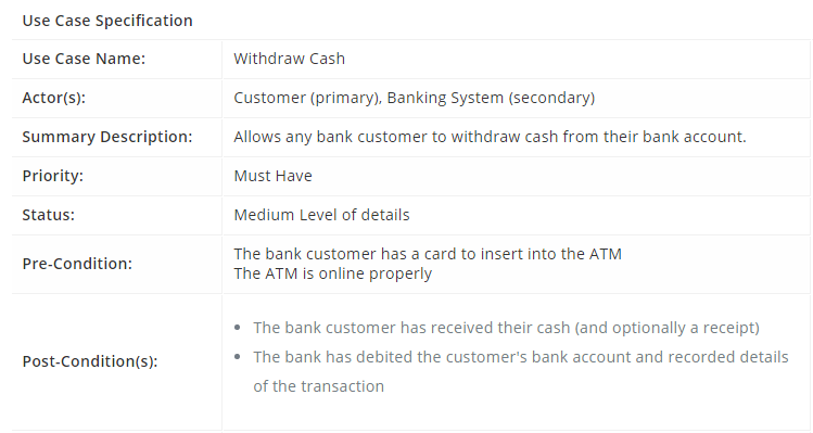 Use Case Specification ? Visual Paradigm
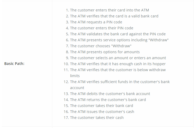 Use Case Specification ? Basic Path
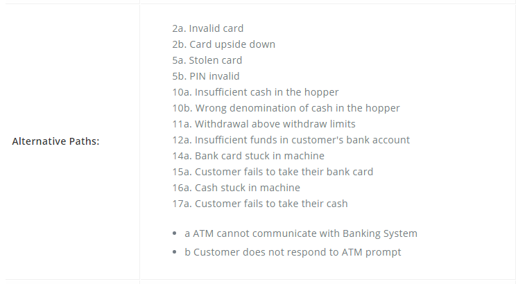 Use Case Specification ? alternative Paths
 Use Case Specification ? Business Rules
 Use Case Specification ? Non-Functional Requirements
Create Simple Use Case Diagrams
If you want to draw casual case diagrams, Visual Paradigm Online will be your best choice. As it is totally free forever, no limitation, Zero setup and configuration.
You Can also use Visual Paradigm Community Edition, it is also free for creating use case for various platforms.
Perform Formal Use Case Modeling and Analysis
If you want to perform and develop use case modeling you are recommended to use Visual Paradigm paid version which enables you to develop a proper and full use case specification as mentioned above.
Do-it-Yourself now with Visual Paradigm Online
Try now and have fun with all these ready-to-edit examples and templates listed as following:
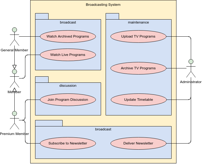
Broadcasting System
ATM
Use Case Structuring Template
Structuring Use Cases with Stereotype

Expressing Multiple Projects Using System Boundaries

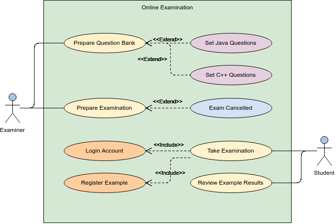
Online Examination System
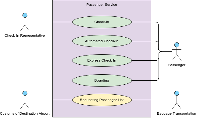
Passenger Service
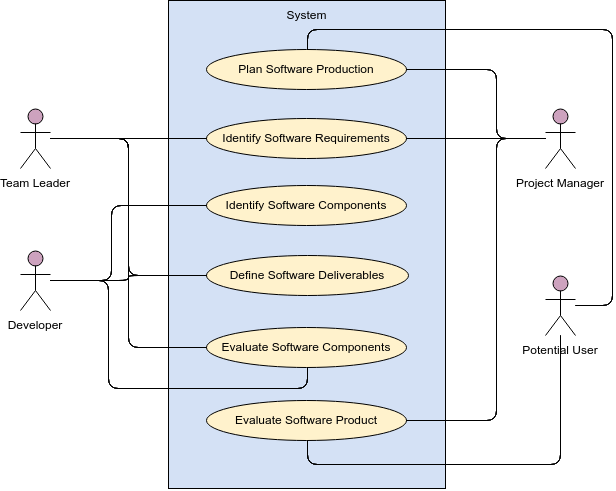
Software Development Management
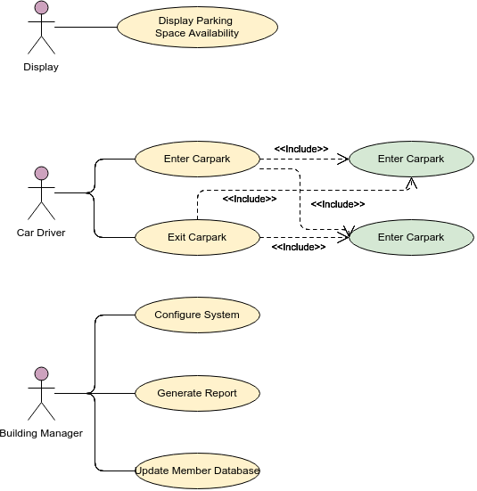
Carpark System
Order Process System
Generalization Use Case

Include and Extend Use Cases
Website (Structuring use cases with extend and include use case)
Use Case Diagram Template
External System as Actor
Bank ATM
