Geotechnical monitoring and instrumentation is a vast field that includes risk management, structural health monitoring, hazard prevention, and early-warning systems using geotechnical sensors. One such geotechnical instrument is the inclinometer or clinometer.
An inclinometer is a sensor that measures the magnitude of slope, tilt, elevation, or depression of an object with respect to the gravity. The tilt indicator sensors are of various types and sizes.
Here we will discuss all the different Models of inclinometers that Encardio-Rite deals with.
What is an inclinometer?
An inclinometer is a sensor used to measure the magnitude of the inclination angle or deformation of any structure. The bent is either depicted in percentage or degrees concerning gravity.
Clinometers are used to measure the slope gradient during activities like tunnelling, excavation and de-watering. Such activities affect the ground that supports the structure.
The installation procedure of tilt indicators depends on the application field. It can be installed vertically to monitor the cut slope or any movement in the shoring wall and embankment. To monitor the settlement of the soil above the spot of tunnelling, clinometers are installed horizontally.
Slope gauges (inclinometers) are of different types. Each slope gauge system requires a combination of equipment and sensors to measure and collect data.
What are the types of inclinometers?
Encardio-Rite deals with two different types of inclinometers which are as follows:
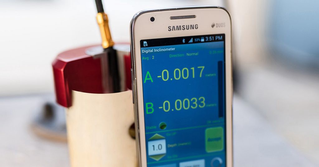
Manual Inclinometer/Digital Inclinometer
A manual inclinometer system is composed of the following components:
- Inclinometer probe
- Inclinometer cable reel (marked at every 0.5 m / 1 m )
- Mobile Readout Unit
- Accessories: Cable Reel battery, Battery Charger, Mobile battery, Mobile Charger
Manual clinometer system is the most commonly used one. For Manual Inclinometer probe, the two MEMS sensors are mounted 90 to each other (biaxial). The probe ranges to 30 from vertical.
The data is retrieved using the traversing application. Let us understand each of the components in detail:
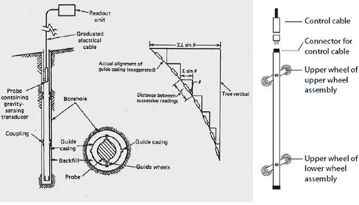
Traversing Inclinometer Probe:The traversing inclinometer probe consists of a couple of gravity-sensing accelerometers in a stainless steel carriage. It contains two sets of spring-pressured wheels that guide the probe accurately at any depth in the casing.
The spacing between the wheels is usually 0.5m. The measurements are done in the A-axis i.e. in the direction of the wheels and B-axis i.e. perpendicular to the A-axis.
The probes for horizontal casing are made differently. The sensors are mounted to measure the vertical displacement while keeping the bottom-tracking wheels fixed.
Inclinometer Casing:The inclinometer casing is used to guide the probe within the casing with four longitudinal wheel grooves, spaced 90 apart. Out of these, only one set of the opposite grooves in the expected direction of the displacement is used.
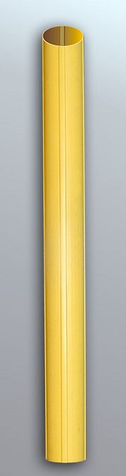
Figure 1: Inclinometer Casing
The casing is generally installed in the ground, within drilled holes and the annular space grouted. However, there are other installations where the casing is embedded in concrete structures.
The casing connection seals out soil, grout, and other material while keeping the grooves clean.
Inclinometer Cable Reel:The inclinometer cable reel is attached to the slope gauge probe and readout device. It is used to transmit electrical signals during measurements and serve as a precise, repeatable depth control for the probe.
The cable has a distinct design and is constructed to provide long-term longitudinal stability. It is made essentially to serve as a measuring tape. In other words, it is made to be durable, waterproof, non-stretch, non-shrink with a high torque resistance.
Mobile Readout Unit: The mobile readout unit is used to record the data at each depth interval. It is capable of storing multiple data sets and can perform field checks to verify the validity of the measurements.
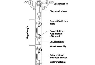
In-Place Inclinometer
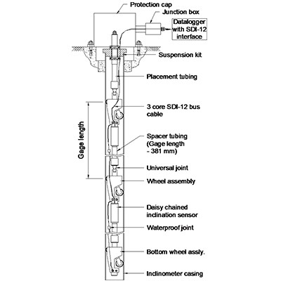
Figure 2: In-place inclinometer general placement
An In-place Inclinometer consists of the following components:
- Bottom wheel assembly
- In place Inclinometer sensor..[Continue Reading..]

